| Changing out B+ filter caps seems to give lots of folks trouble when it really shouldn't. I believe the first one to draw a lot of email was the G05 802 deflection board caps C100 & C101 which would apply to the WG V2000, as well. That was closely followed by the B+ filter used on the G07 chassis. B+ filter replacements on many other monitors drew emails to a lesser extent, but pointing to the G07 guided those to fruition. The current one is the subject of this page... the Sanyo 20EZ B+ filter. The one question that seems to preceed installation is the voltage rating. The OEM is a 470uf160v & we ship 470uf200v snap-in caps as replacements. The voltage rating of a cap is how much voltage that the cap can safely handle. With the OEM cap it should be able to handle an applied voltage around 160 volts & exceeding that voltage will turn the cap into a cherry bomb. The 200v caps we ship only serve to increase that safety margin. The voltage rating a cap can withstand in a circuit is only limited by it's physical size. If your PCB only has a one inch plot for mounting the cap then you obviously cannot mount a two inch in diameter cap rated at 500 volts, but if that 500 volt cap will fit in the designated area & has the proper microfarads your good to go. BTW: Ops never let the fact that the cap was too physically large to be mounted... just remembering the one I found in the bottom of a cab hanging by a lamp cord connected to the PCB :-() After getting the voltage issue behind & moving on, the next question is always about fitting the mounting holes.... it doesn't line up... the holes are too small... the holes are too close... the holes are too far apart & etc. Most chassis' will accomodate any cap layout via multiple silked positions. Unused holes will be solder filled & only need to be cleared if they are the ones you need for your particular cap. 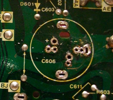 K... here's the C606 B+ filter mounting pads completely cleared out & you can see that there should be a pair of mounting holes for any cap type or size you can imagine. 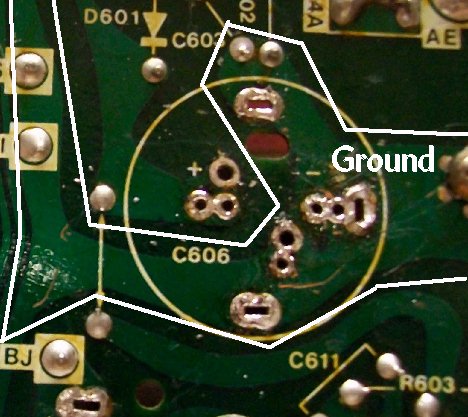 The ground trace is outlined above & it's easy to see that finding a hole won't be hard. 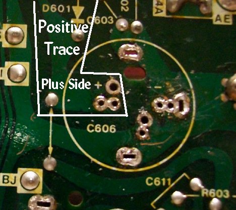 The same goes for your positive lead... if need be, you can clear all the holes to find the ideal pair for mounting. 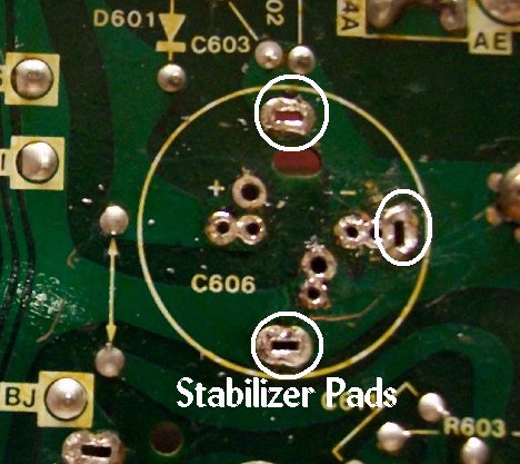 There are even stabilizer pads to use a can-type cap & as you can see, they are all a part of the ground trace, as well, and could be used as a ground pad for your new cap, also. 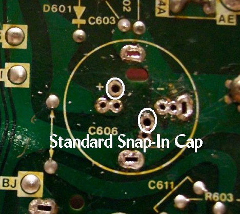 Here are the holes you need for our cap & it is good practice to backfill any unused holes with fresh solder. 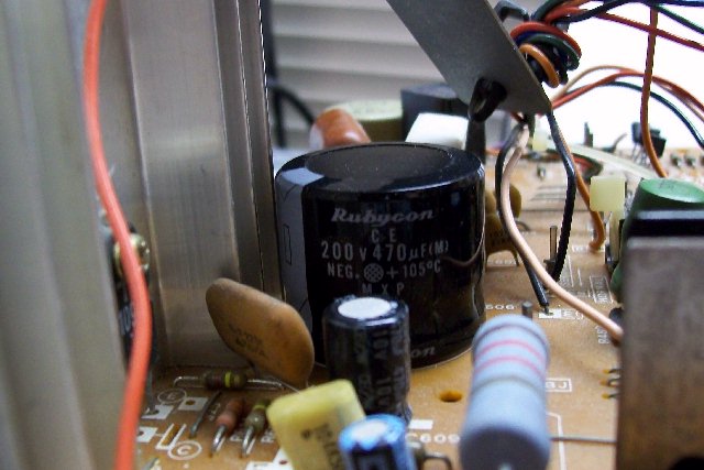 And... the coup de grâce... finished result! Happy Gaming... |