|
Over the past ten years I've been asked at least one hundred times how to get audio amplification cheaply for use with game boards that require a separate amplifier or to use in a cab for stereo, or faux stereo adaptation. It seems no one wants to lay out big bucks just for sound & would rather devote a little labor in attaining it, making for a new fun project in the process. The answer that I always give is to buy a cheap pair of amplified PC speakers. Everything you need is right there and at a fraction of the cost of an a standalone amplifier.... probably better than one you'd make from a scratch kit, too. These sets sell from $8 to $20 new, but often times you can pick up a used set at local weekend flea markets for $3 to $5. Many times when I've suggested this the person responds with, "oh, I have an old set I'm not using" or something like my buddy use to build PCs & has a whole garage full of them.
A lot of people had trouble grasping this from just my emails, so I've grabbed a Mr Do & Mr Do's Castle PCB from the warehouse & will walk through adding this cheap, little or no money, amplifier to an adaptor allowing sound when used in a JAMMA game. 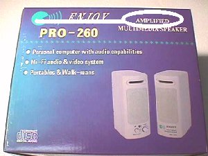 The obvious first thing needed is the PC speakers. I grabbed one of the sets that are on my Flea Market Page at $10. If you're looking for these locally keep in mind that the keyword on the package is going to be "amplified" as many older sets were not amplified & therefore, contained no audio amplifier inside :-( I found cheap unamplifed sets like this all over the net at $4 to $7 a pair, so the keyword must be stated in the ad or on the box & sometimes a little more expensive pair may contain a better grade amp, as well. Another thing to keep in mind when looking for these is the operating voltage. I've found that ones that operate on 6 volts, battery or adaptor, don't seem to work as well as 9 or 12 volt ones. You are actually better off looking for a set that operates on 115VAC. As with most electronics that operate on 115VAC, the voltage is dropped to 12 volts with a stepdown xformer inside & 12 volts DC is readily available in your cab. 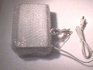 Okay... you've got the speaker set you want to use & once you open the box all you need to look for is the one with all the main cabling on it & take it out .... it's usually on the top, so everything else can be left in the box untouched. 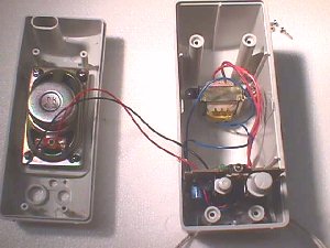 Remove the 4 screws from the back & separate the 2 sections leaving the wires between each component until you can ID them. You can now see the amplifier board that the mfr has hidden away in the case. Most just slide in & out of a track on the case & are easily removed. If you are unfamiliar with the wiring to & from the amp bd you may want to jot down the wire color code & their purpose. The red & black wires in the pic above, going to the left, are obviously going to the speaker itself. You can cut those wires about an inch from the speaker leaving plenty on the amp side for reconnection. 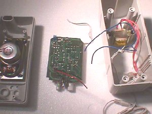 Next look for the AC line cord coming into the case & you will see that the wires go to the input side of the stepdown xformer. Just in case you got ahead of yourself here... make sure that the line cord is NOT plugged in!! It's not :-) Okay, look for the output wires of the xformer & follow them down to the amp bd. It's not going to help you for me to refer to colors because they are going to be different from one set to another, but I will use them only as reference in the pics I have taken. In the pic above the output wires from the xformer to the amp bd are blue. Since we are not using the xformer for power you need to cut those wires about an inch from the amp bd... that inch leftover is just for a marker, so that you don't lose sight of the power entry. The only wire left at this time is the input wire... the wire that has a plug to connect to your PC. This wire should be cut about 6 inches from the amp bd to make sure you have enough to work with. That's it!! You've extracted a good amplifier. The basics are a pair of wires to attach to the speaker & an input cable to attach to the game bd's output to be amplified. All that remains is power to the amp bd & we'll add those wires, so that it can be color coded to DC power after a little more modification. 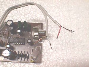 Let's prepare the input wires first. They are shielded wires, so the ground is actually the wire mesh that is wrapped around the center wire. You need to strip these back & separate the leads. Take care with the center wire as it is usually a small gauge that will break very easily if too much pressure is applied. I'm not using stereo for these Mr Do bds that only output mono, so I'm going to combine both grounds & both center wires to feed the mono output to both channels of the amp.  Solder the ends of this pair to keep them from unraveling while working on this bd & it will also prepare them for soldering to the adaptor. 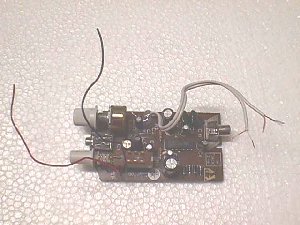 Okay.. let's get the power entry fixed up to go now. 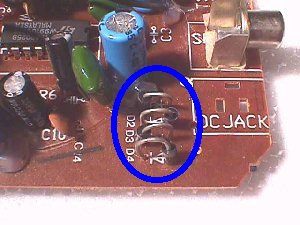 You need to locate the bridge rectifiers that are fed by the 2 AC in wires that were left as markers. One type of bridge is pic'd above... it's diodes are installed vertically & I've put the pic here just for reference in case you run into a setup like it. 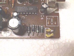 This is the typical bridge assembly most often seen in electronic equipment. We do not need this bridge nor the AC markers that were left, so we are going to remove them, but first let's flip the board over to see where we are going to add our DC power wires. 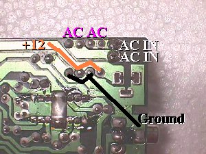 You can see from the pic above where your +12 volt orange wire should be attached & where the ground needs to be attached. All PCBs are not going to be traced out like this one, so the easiest way for you to locate the + & - of the bridge is to see which of the 2 conjoined pads also ties into metal ground pieces such as the speaker jack, metal casing of the volume pot or the ground braiding of the shielded input lines. This one will be -, obviously, & the remaining 4th junction has to be the + by the process of elimination. Four tie points, 2 are AC & now we know the third is ground, so the 4th has no choice but to be the plus DC voltage tie point, so you don't even need to know how to read a diode or bridge :-() Another quick clue would be that your 12 volt line is generally going to be tied directly to the on/off switch. 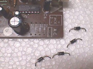 K... now you can pull the four diodes that comprise the bridge & the two marker AC wires that were left behind. This particular PCB has AC... IN.... Speaker & others imprinted on the board, but that's not something that will always be there, so you have to have an idea of what goes where. 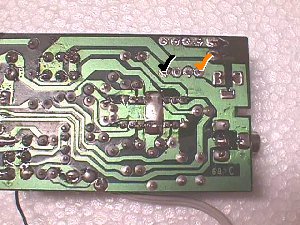 Next cut two pieces of 20 gauge wire... one orange & one black... about 6 inches long & strip the ends. You can use either pair of empty diode positions to feed these wires through the bd. I chose the 2 in the pic above & the orange wire goes to the pad that was established as the +12 volt, while the black goes to the one established as the ground. 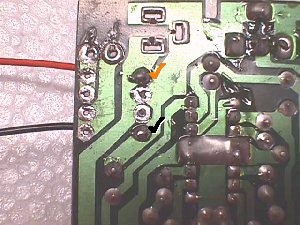 After soldering the wires in place make sure you don't have any solder splashes. You can fill in the rest of the empty holes or just leave them. Next... twist the two wires together for use later on. 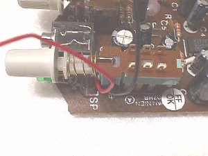 This amp bd is only going to power up & down with the game bd it is used with, or the cab it is put in to, so we don't need the switch on the amp bd. Remove it & if it's like the one in the pic it can be used as a replacement on one of your Williams games when needed. 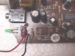 Now that the switch has been removed the pads must be jumpered to be in the "on" position all the time. 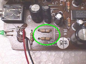 In the pic above I've jumpered the switch closed with zero ohm resistors, but you can use bare wire, insulated wire or even a common paper staple or clip, if nothing else is available. 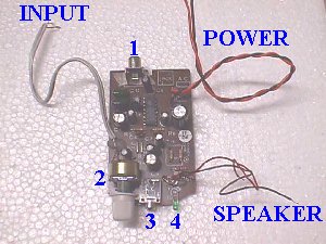 Ready for mounting! I left the RCA jack (1) in place for an easily added speaker...PnP. The volume control (2) obviously had to be left on the amp bd. The headphone jack (3) was left for those late night games where you don't want to wake the boss & the LED (4) was left as an idiot light. 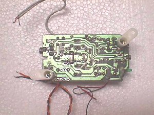 For the Mr Do adaptors I've simply put a gob of hot glue on opposite corners in the flattest spots available & stuck a couple PCB feet in it. It would be best to place one of the feet under the volume control to help support it when in use. 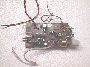 You could mount this to a piece of wood & connect all the I/O up in one connector with a mate in your cab as a permanent cab amp. The possibilities are unlimited... wire in a couple speakers for stereo operation... relocate the volume control from the amp bd to the coin door area... switch it for mono single, dual or stereo operation... wire it to simple PnP connectors inside the cab... you are limited only by your skill & knowledge level. 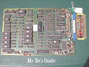 K... I'm starting with the Mr Do's Castle board above & while I'm not going to go over the adaptor building itself... covered many other places... I am going to put a few notes that may be stumbling blocks on this particular bd. 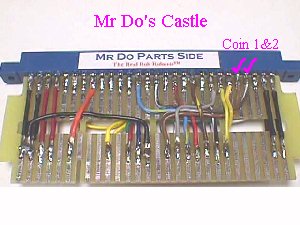 The first thing is that this bd uses a little wiring wizzardry between the coin switches & coin meters. The coin meter voltage actually is used to pull up the coin switch I/O lines, so just trying to connect directly to the coin lines will result in not being able to coin up a game. Obviously, you don't want to mount coin meters on an adaptor nor do you want to rewire your coin door to operate with this bd. Hacking a classic bd is out of the question, so a little wiring wizzardry has to be accomplished on the adaptor itself. 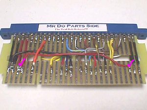 The first thing to do is get 5 volts down to the other end of the adaptor & this can be done with a red jumper wire from the 5 volt pad down to pin 26 on the finger bd. Solder it on at mid trace. 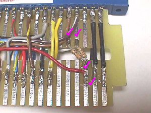 Now you can add a pair of 330 ohm pull up resistors to the coin lines as pic'd above. You can cut the trace going back to the JAMMA harness just in case pin 26 is used & switched on your control panel. This will eliminate the possibility of accidentally shorting your 5 volt line to ground. 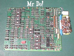 This same adaptor can be used on the Mr Do game bd. The Mr Do, however, has pin 26 on the bd going to ground, so you don't want to use this position on the adaptor bd side. It is not necessary to connect up all 6 ground fingers on this end of the bd... the standard 27,28,e & f are plenty adequate along with the other end's 1,2,A & B. 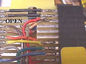 K... it's 4:30AM & I'm not sure I understand what I just said, so I'm going to take another stab at it. If you have a Mr Do adaptor already, it may have pin 26 & d wired to ground on the adaptor as the last 3 positions on the PCB are a single wide pad. If it is jumpered on the adaptor you need to remove it & if you're building an adaptor to Mr Do, don't use the position marked in the pic above as OPEN on either side of the board. As far as the pull up resistors go, they can be left in place even though the Mr Do doesn't use the same coin configuration & does not require it to be done. 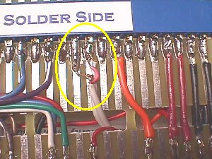 K... let's add the amplifier starting with the input since it connects on the solder side of the adaptor. The audio + output is on pin L & the audio - is on pin M. 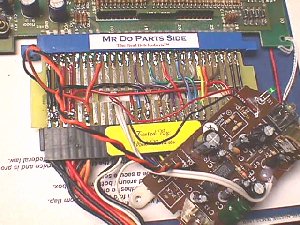 Now the twisted pair for power needs to be added... orange wire to 12 volts & black wire to ground. Only the speaker wires to hook up now.... red to JAMMA side pin 10 & black to JAMMA side pin L. Give it a quick once over, put a piece of cardboard between the adaptor & the game bd to act as a temporary insulator & fire it up for a test run. 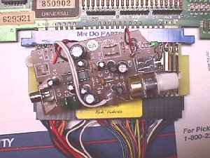 Everything works fine... put a dob of hot glue under the two PCB feet on the amp bd & stick it to the top of the adaptor where it best fits & you're done. If you're not too fussy about your sound you could strip out the leftover speakers & incorporate them into your cab. As I said, the switch could be used for a WMs game & the stepdown xformer could be used for powering coin door lamps in a project.... leaving only the box & plastic housings to chuck out. Incidently, the 2 boards & 2 adaptors from this article are for sale at $50 each piece or $90 for either bd/adaptor combination. Happy Gaming... |