Here's a question that I'm asked a minimum of once a week, & most times more than that, so I guess it is time to throw up a quick response here. The basic question seems to be 'how do I know what's what on this bridge rectifier?' and the answer is easy, although there are some variances and some multiple ways to tell. Basically all you need to know is which terminal is the + terminal & the others fall into place for you. The - will be opposite the + & the 2 remaining terminals will be the AC in feed from the transformer in an 'it don't matter' arrangement :) How does the mfr let you know which terminal is + ? It's done several ways... sometimes a couple different ways on the same bridge... with one way being the + lead is left longer than the rest on a wire leg bridge... the pattern of the terminals will be such that 3 are alike with the remaining one being different in it's position or appearance... and finally, by earmarking the case at the + terminal. Well, of course, there is one other way... labeled! This way would have the + & - opposing each other & the opposing AC terminals marked with this symbol ~ .
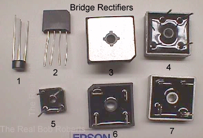
Anyway, the point is that you can often identify a bridge's pinout with it laying upside down in a parts bin if you know what to look for. K... it's time for the pic that replaces the thousand words now, and I'll go over this handful of bridges pointing out what to look for.
I guess the easiest way for a newbie to grasp the polarization is to think of this bridge as though it were a battery. You know that when you put an ordinary "D" cell in a flashlight that the + end has to go toward the lamp and that the - or negative end is the ground for the lamp. Well... this is basically the same, so your cab wires coming from the negative terminal of the bridge are the grounds, while the wires that are going to the + terminal of a big filter cap are the positive DC wires. That should answer the Q of what color wires are on the bridge in my game? It really doesn't matter so long as you know that the 2 AC terminals have the wires attached that go to the transformer, and the - terminal is going to ground while the + terminal is the one that supplies the DC voltage & needs to be filtered through a big cap.
Oh.... I don't get a reading across the 2 terminals...do I need a new bridge? Almost forgot that Q ;) Remember to measure across the 2 opposite terminals marked, or determined to be, AC with your meter set to measure AC and do not try to measure it to ground. Then set your meter to DC voltage to measure the DC from the + terminal to ground... sometimes better to locate a remote ground. This will verify that your ground system is intact, providing you get your expected DC voltage reading.
Addendum:
I get variations of this Q quite often, such as: I don't see the bridge used in the Atari AC power "brick"....My Tempest manual says I need a MDA3501 bridge & I can't find one....What's a suitable replacement for my T3501... and so on. Like diodes & many other components, the key is usually in the part number. I have added more info on the Parts Page beside each one listed to better aid you, but I will put a brief note here, as well. In both the examples cited above the bridge is ...from the part number.... a 35[amp]01[ 100 volt]. Generally speaking the first digit/s will refer to the amperage that the bridge is capable of handling & the ending digit/s the voltage it is capable of handling. As Scottie would say...if you put a 2501 in place of the cited bridge, she's gonna blow!... since the bridge is only able to handle up to 25 amps of current even though the 100 volts is sufficient. You could go to an "02" 200 volt, "04" 400 volt or higher & still end up with a blown bridge. You need to at least meet both amperage & voltage of the original when replacing. A good replacement for the cited bridge would be a 3502... disregarding mrf's prefix or suffix.... for 35 amps & capable of handling 200 volts before popping a leg. Much like sister components.... diodes, capacitors & resistors, you can safely go beyond specs, but not below.