I Want To Build a Game!
by Bob Roberts
I have an empty cabinet. How do I put a game in there? Newbie question of the year 1998. Hmmmm....here's a rough idea of the things you'll need for a Jamma cabinet & what is involved in wiring it up. Just the very basics instead of a detailed, in-depth version laced with technical jargon.
You'll need some 18ga wire to wire up the AC portion of the game first, after you have laid out a plan as to where you are going to want everything placed. I'll start off with the 10' or longer AC line cord. Fish it through the hole in the cabinet designed for this purpose & secure it with a cable clamp leaving enough line to run to your AC filter.
Ok! We have 110VAC into the cab and now we need to fuse the hot side & put an on/off switch in line.  Run the neutral wire & the green ground wire from the line cord directly to the AC filter inputs making sure that the green wire is connected to the metal case of the filter, either with the internal connection if it is a wire type, or the case tab if it is a quick disconnect type. (This is where your ground line will begin to tie all the metal in the cab together...just run a braid or 18ga preferably green wire from the metal on the filter to the power
supply, coin door, control panel [metal] and monitor frame.) The hot side of the AC cord can now be fed though a fuse holder with a 3 amp fuse in it, and on to the other side of the AC filter.
Run the neutral wire & the green ground wire from the line cord directly to the AC filter inputs making sure that the green wire is connected to the metal case of the filter, either with the internal connection if it is a wire type, or the case tab if it is a quick disconnect type. (This is where your ground line will begin to tie all the metal in the cab together...just run a braid or 18ga preferably green wire from the metal on the filter to the power
supply, coin door, control panel [metal] and monitor frame.) The hot side of the AC cord can now be fed though a fuse holder with a 3 amp fuse in it, and on to the other side of the AC filter.
7/4/2 Addendum:
Several questions are arising on a daily basis now... more than a FAQ... so I will insert the answers here as another paragraph to save time. The first one is in regards to what size fuse to use in the AC line & it should be as stated above, but I guess overlooked a lot for some reason, as a 3 amp fuse. This only needs to be a standard fast/quick blow fuse of 125VAC or better. Next is in regards to whether or not a second fuse is needed in the neutral line. You can certainly fuse both lines if you want to do so, but it is not necessary. This sort of pertains to the next question, as well, and that is to do with switching both hot & neutral lines.
Again, you certainly can if you so desire, as did many game mfrs... in fact, they also switched both lines through the safety switches in many cases... but simply switching the hot side as in your common household light switches is perfectly acceptable. The switches used in games are Double Pole Single Throw (DPST) & essentially this means that you have 2 switches in one case that are both either on, or off, at the same time when toggled. There are 4 terminals on this type switch... 2 on the end & 2 in the middle... and you only need to use one end position & one middle position. The switches are independent inside the case, so the exposed terminals do not pose a shock threat to you, however, there are also many DPDT (Double Pole Double Throw)switches in games & this is where a few of you are having a bit of trouble :-( This switch has 6 terminals (poles)... 2 center & 2 on each end... and a basic way to look at these switches would be as though you cut the body in half right down the center, long ways, creating 2 separate & independent switches. If using one side only, you are still safe from exposure to a shock on the UNUSED side! Depending on where you hook your fused hot line, it is possible to have 120VAC on the exposed terminal when the game is switched off. I'll tell you how this can help you after, but for right now I'll try to explain this as simply as I can. Maybe a pic is order:
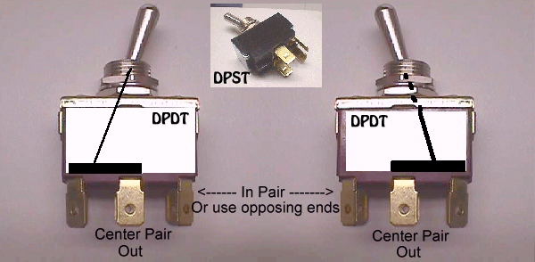
OK... OK... stop laughing at my drawing :-( Y'all know that I can't even spell ARTIST :-()
My attempted drawing is suppose to show you what is happening inside the switch & you can see that if you ran the hot lead coming from the fuse to a center terminal that it's resulting output would be switched to one or the other end terminals ALWAYS! This would mean that the input 120VAC would be feeding the game when in the on position, but when in the off position it is feeding the exposed bare terminal. This can cause your eyes to open widely if brushed against while poking around in the game that you think is off & safe! The remedy is, of course, to feed the input to either end using the center to feed the game. The exposed terminal is no longer a shock threat.
FAQ: In most of my games the earth ground ends at the AC filter & does not tie the metal cab parts together. What's the deal here?
Yes it's true that inert cab metal grounding is often nonexistent or it has the CP excluded due to minor shocks between games when one is improperly wired... it has the monitor frame excluded due to herringbone interference presenting itself on the screen... it has the PS excluded due to chattering &/or interference, and there are many varying opinions on this within the industry & all I can say on that is that any shocks that I have gotten from inert metal vid game parts since their inception, has been from earth grounded pieces. I have never received a shock from an inert vid game metal part that was not tied to earth ground!
Oh... before I run off, I had said I would tell you how a DPDT switch could be used to your advantage in a cab. Over the years there have been many hobbyist that wanted to put 2 games in one cab, but totally independent (less monitor sharing) of each other & this is an easy way to accomplish just that. First you need a DPDT switch that has a center detent for an off position... standing straight up in the center will be the off position for both games. Simply wire the hot side from the fuse to the center terminal that was taboo in the single game cab, and jumper it through to the other center terminal... making for one entry into both sides of the switch. Now you'll have 2 hot outputs on each end of the switch. Using one side of the switch you can supply either game in the cab with a switched hot depending on which way you toggle it on... you know, the bare terminal that was going to shock you in the single game cab can now be supplying the input for a second game instead of laying in wait to surprise you :-( K... you still have a hot terminal on either end of the switch (same side) & this is used to feed the isolation xformer it's hot so that it can be shared for both games. Both of the remaining output terminals on the switch should be connected to the hot input of the iso. What this accomplishes is that when your switch is in the off (center) position the iso is also off, but no matter which game you flip on, the iso will be getting a hot feed, as well. That only leaves actual vid/sync sharing & sometimes just feeding both to the monitor input works fine, but to keep them isolated as separate games you can insert 1N4007 diodes in each line (cathode toward the monitor) before it goes to the monitor input header as blocking diodes preventing any feedback when combined. This is easiest to do by making up a "Y" connector with the blocking diodes inserted into it. Then you can plug each game's vid/sync signals into your "Y" & plug it into the monitor header with no resulting hacks to be undone in the future. Sharing a CP, if both games are similarly controlled, can pretty much make this a flip of the switch transformation.
We now return you to your regularly scheduled program :-)
On/off switch...I always located these on the the top righthand side of the game for convenience purposes....some mfgers had them at that back-bottom-middle-impossible-to-get-at position, and I just couldn't stand that. Run your 18ga wires from the AC line filter output tabs to the power switch.
We have a fused, switched & filtered AC line at this point & need to route your AC to the needed destinations. 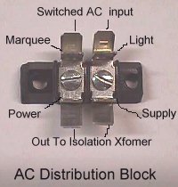 The easiest way to do this is to have an AC distribution block with .25 quick disconnect tabs.....4 on each side. Run your 18ga AC wires back down from your power switch to this AC distribution block & utilize .25 QDs to attach them to the terminals, one on each side. Now you have 3 terminals on each side left to use. Use the first pair to supply AC over to your swiching power supply....the second pair will be used to supply AC to the input of the monitor isolation transformer...and the third
pair will be used to supply AC to your marquee fluorescent light. Remember, you have passed the input of this distribution block, through your on/off switch at the top of the game, so when in the off position, there is no power being supplied to this block, and therefore all things attached to it are now off.
The easiest way to do this is to have an AC distribution block with .25 quick disconnect tabs.....4 on each side. Run your 18ga AC wires back down from your power switch to this AC distribution block & utilize .25 QDs to attach them to the terminals, one on each side. Now you have 3 terminals on each side left to use. Use the first pair to supply AC over to your swiching power supply....the second pair will be used to supply AC to the input of the monitor isolation transformer...and the third
pair will be used to supply AC to your marquee fluorescent light. Remember, you have passed the input of this distribution block, through your on/off switch at the top of the game, so when in the off position, there is no power being supplied to this block, and therefore all things attached to it are now off.
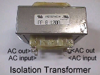 To finish off the AC portion of wiring, you will need to run a couple 18ga wires from the monitor isolation transformer outputs to the monitor AC input and you should be ready to Jammatize the game now....the easy part! Before you go on, if you want, you can plug the game in and power it on for a few seconds to verify the power supply LED lights & the marquee lamp & just listen for HV voltage build up in the monitor. Do not leave powered more than 15 seconds or so... just enough to let you know you are on the right track, and not long enough to damage the switcher with no load on it.

Hmmm...you're right on track & the switch turns everything on & off, so now I'd start with one of the many $10 to $20 Jamma pcbs & mount it where you have planned to have your pcb located & attach your Jamma harness to it. The first step is powering your pcb with DC voltages, so you will want to run the power wires from the Jamma harness over to the switching power supply.
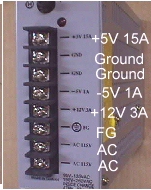 The typical generic harness has 4 to 5 feet of wire and since your pcb is where you plan to keep it, cut the power wires to have a minimum of slackness to them. The shorter the run from the pcb to the power supply, the better. I like to keep them under 30" long & terminated with spade connectors with a minimum of 3 18ga wires for 5 volts, 3 for ground, & 1 each for 12 volts & -5 volts.
Ok, so without going into a couple more pages of details, we basically have DC power to the pcb, so lets run the easy one next. Mount your speaker, if your empty cab didn't already have one in it, & run the Jamma speaker wires to it, preferrably with a plug in line for disconnecting it separately.
Next run your Jamma monitor connections...RGB,gnd & sync...up to the monitor input header following the pinout for the monitor mfg. The basics are in place now, and you can go ahead & power it up for a smoke test at this point, making sure that any loose wiring is not laying on the fuse block or across the pcb or other place that might cause a short.
You're at the decision point at this time. If you adjust your power supply's 5 volts so that you have 5 volts on the test pcb's pads, and you have a good picture & sound, if the pcb is set for attract mode, you're good to go to the next stage, and if not, perhaps it's time to buy a Jamma cab :(
Everything is down hill & real easy from here, beginning with running the Jamma wires for the control panel, which you should have already populated with the joysticks & buttons of choice, by now, and running the wires to the coin door for coin switching & any other options you choose.....coin meter.....coin lamps...test switch....credit switch ....etc. 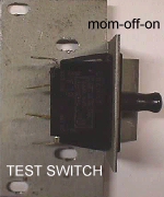 I always used a safety interlock switch & mount for a test switch as some games require only a momentary close of the switch to go into test (push it in like the back door of a game) while others require the switch to be on all the time you are in test mode (pulled out like on the back door of a game while you are working on it).
If you want coin door lamps and/or coin meter, you can run a 12 volt line from the Jamma harness to the coin door for this purpose, but make sure that these are also 12 volt lamps &/or meter.
This should get you started in the right direction without getting into to much technical detail.
Happy Gaming.............
All the parts pic'd here are available on the Parts Page .
|
Help Page Index Big Bear's Bulletin Board
Site Index