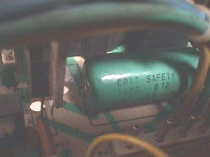
I'm asked about the C36 capacitor at least twice a week & it invaribly is in regards to replacing a shorted one... one that has 4 legs, is green or blue, and has the words "Crit Safety Cap" imprinted on it - the name that has stuck over the years. It is actually used for retrace, but I guess you could call it a critical safety cap if you were to replace it incorrectly... leaving the HOT's collector free floating.
 These are found in early versions of the K7000, later versions replaced these with standard two legged radials, but PCB traces were also modified to accommodate. You'll have to do your own modifying to replace these with the common type, as the old chassis depended on this cap to complete the HOT's path to ground & flyback winding. 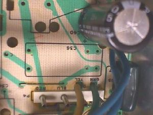 The two legs on each end of the old capacitor should measure a dead short to each other as they are electrically the same point & as you can see in the outlined block above for C36 (upside down), the two end legs are actually needed to complete the circuit on the PCB. 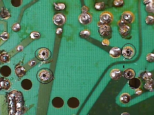 Above is the solder side of the board after removing the cap. The first thing to do would be to connect the circuits back together. As I've said in other docs on the Help Page, I always saved the clippings from cap replacement, resistors & other components to use for jumpers in situations like this. Easy & cheap :-) 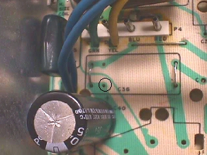 Rather than square the ends of the jumper to 90ş, I prefer to leave them arched & this case is a good example of why I do that. It leaves a nice tie point, whether it be for a scope lead clip while you are working on the chassis or for mods like this one. 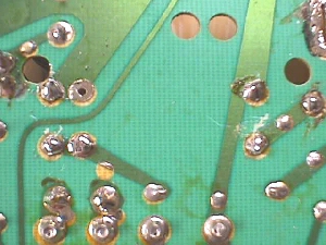 After soldering in the jumpers you need to remove the solder in one of the two parallel dead (unused) thru-holes next to the jumper on the left above. Flip the chassis over and make a hook with one lead of your replacement cap. Hook it up under the jumper closest to the HOT & guide the other end through the hole you opened up & solder this end in from the underside.  Now you can finish the hook end by closing the hook around the jumper, aligning it to suit your taste & then soldering it to the jumper. Once cooled... ball the joint with solder to hide any pointy place that may lend itself to arcing. If you've missed balling in the Help Pages elsewhere, it is just melting/melding a round ball of solder onto the finished joint to encase it. Happy Gaming.... |