I "hear" this a lot & it's usually accompanied by ... I just want to know which way is the correct way to put it in & don't care what it does, be it blocking, single, half or full wave rectification, or if it's just in there to add to the weight of my game! Here's a couple examples, maybe oversimplified, that should help you determine the correct way on your own. First I'll paste an excerpt from the WMs Battery Conversion Page that might prove to be of some help:
This will work in many other cases, but beware that you cannot just drop this in place of a ni-cad without defeating the charging system. This can be done by installing a blocking diode in the + line. I'm quite frequently asked how one can tell which way to install the diode. I think it is easiest for a newbie to think of the cathode stripe on the diode as a gate in the front yard fence that only opens outward as you are leaving your home, with the body being your walkway, of course. No one can walk up to your gate & pass through to enter your home, but you can walk down your walkway (diode body) and out through the gate. A diode with the complete symbol imprinted on it will have an arrow with it's point butted up to the cathode band signifying the direction of flow. If used as a blocking diode for a lithium battery you would want the cathode on the end furthest away from the + terminal, thus allowing the flow down the walkway to the components, but blocking at the gate any flow back towards the battery.
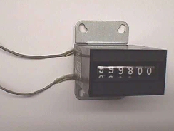
A common app that may even need 2 diodes would be coin meters, if used.
Your meter may have a diode installed inside to prevent spikes, called a clamping diode, and if it does, you'll find a + & - sign on the side where the wires come out as pic'd below.
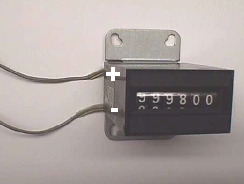
Most meters with internal diodes will have color coded leads to aid in identifying polarity with red for the + side & black for -. The + side will connect to your voltage source, which should match the voltage rating found on the meter, as well. The - side will connect to your pcb's circuitry for pulsing the meter low (ground).
If your meter does not have the internal diode you can put your own across the 2 leads. Since you have no polarity at this time, it makes no difference which way you install it, but once installed, the cathode (banded end) becomes the + side & must connect to the power source. The other side will go to your drive circuitry of your pcb or whatever else you may be using.
If you want to install a coin meter & your PCB doesn't have any drive circuitry, you can connect it directly to the coin input circuitry. As your coin switch closes to pulse the input for your PCB, it also pulses the meter. This will work well with a 5 or 6 volt meter, but if you are using a 12 volt meter you do not want this 12 volts feeding back into your circuitry on your pcb & damaging it, so you can use another diode to prevent (block) this from happening. If you install a diode in the coin switch line coming from the PCB in the direction of the arrow with the banded side (cathode) towards the meter & coin switch it will block the 12 volts from feeding back into the board circuitry. Sound familiar.... it's the same blocking action used on the Tron/MCR battery conversion to stop the on-board charging system from feeding into the lithium battery.
Here's a recently asked Q that will fit right in here, about replacing the diodes on an Atari xformer assembly for an Asteroids.
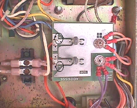
From the pic you can see that the older ones were not plainly marked with a band for the cathode side. They have a very thin pic of the symbol depicting the direction of flow on the side, but it is quite often worn away over time. In almost every instance you will find the symbols stamped on your PCB. In the case of this small PCB that mounts to the "Big Blue" capacitor, the symbols are very small themselves, so I circled them above. If you look closely you'll see the entry arrow butting up to the cathode band which faces the capacitor. This board with the 2 rectifiers forms a conventional full wave rectifier. Later Atari assemblies came with a full wave bridge rectifier. You might also note the + symbol on the pcb signifying the positive side for the Big Blue capacitor.