Updated 10/20/01
I get asked this all the time & usually paste this answer from my files, but I thought it was time to put it up here where I don't have to keep pasting it all the time.
I want to rip the power supply out of my Donkey Kong & put in a new switcher and need to know how to do it the easiest way. Why on earth do that, when you can have the best of 2 worlds.
Who knows what a DK will be worth 10 years from now.... Here's how I would attack installing a switching power supply to preserve the integrity of the machine.
 I would get 2 sets of Molex .093 12 position connectors &
2 sets of Molex .093 9 position connectors & install one set
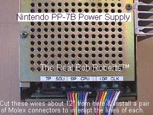
in each line...the ones that go to 9P & 10P on the power supply.
These would be straight thru line interrupt plugs & the system
would still operate as designed with a good PP-7B linear PS.
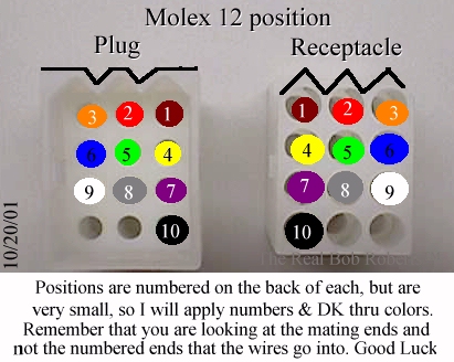
The 9 pos for 9P & the 12 pos for 10P. I would install them about 12 inches down the line from the original power supply. When interrupting any lines, or when wiring up a new game, the best way to install connectors is to
always put the receptacle portion, with sockets, from the power source.
This would be from the AC in...from the DC power supply....from the game pcb to video in & etc, always working away from the source & leaving the pins & plugs for the passive connections.
I would get 2 sets of Molex .093 12 position connectors &
2 sets of Molex .093 9 position connectors & install one set
in each line...the ones that go to 9P & 10P on the power supply.
These would be straight thru line interrupt plugs & the system
would still operate as designed with a good PP-7B linear PS.
The 9 pos for 9P & the 12 pos for 10P. I would install them about 12 inches down the line from the original power supply. When interrupting any lines, or when wiring up a new game, the best way to install connectors is to
always put the receptacle portion, with sockets, from the power source.
This would be from the AC in...from the DC power supply....from the game pcb to video in & etc, always working away from the source & leaving the pins & plugs for the passive connections.
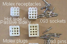 The reason for this is fairly simple in nature, you want the source to be fully insulated & not exposed to an accidental shorting, such as what could be done with a spare pin falling into the plug/pin portion of the connection...hot side...smoke , smoke, smoke...passive side, not a problem since that side is never hot when the connection is broken.
So, the top set of receptacles in the pic to the right, will terminate the wires from the PP-7B power supply & also the wires coming from the new switcher, while the ends of the wires going down to the game pcb will terminate with the bottom passive plugs with pins which can handily plug into either source of power .....PP-7B or switcher.
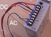 The second set of plugs going down to the switcher should be 15" to 18" long & I would opt to use the Jamma standard color codes for wiring, e.g., black = ground, red = +5 volts & etc, to terminate with spade connectors that will easily connect to the switcher terminal output screws. I recommend using 18 gauge wire for this new short run, as well. Since the AC input to the PP-7B is only 100VAC, I would simply unplug it while the switcher was in use, and for switcher power, I would tap into the 120VAC line just before the game's
transformer input...so that it is a switch controlled AC input to the switcher. I would also put a 2 position Molex .093 connector in this AC input line for easy removal of the switcher. Remember that the receptacle side will be coming from the transformer, so that when, or if, it is unplugged, there will be no existing shorting potential.
The second set of plugs going down to the switcher should be 15" to 18" long & I would opt to use the Jamma standard color codes for wiring, e.g., black = ground, red = +5 volts & etc, to terminate with spade connectors that will easily connect to the switcher terminal output screws. I recommend using 18 gauge wire for this new short run, as well. Since the AC input to the PP-7B is only 100VAC, I would simply unplug it while the switcher was in use, and for switcher power, I would tap into the 120VAC line just before the game's
transformer input...so that it is a switch controlled AC input to the switcher. I would also put a 2 position Molex .093 connector in this AC input line for easy removal of the switcher. Remember that the receptacle side will be coming from the transformer, so that when, or if, it is unplugged, there will be no existing shorting potential.
Done in this fashion, you would now have a PP7-B & a switcher & could plug to either one in less than a minute, being sure to unplug the unused power supply. If your PP7-B is in need of repair, you can run from the switcher until such time as you decide to repair the original or if you sell the game for some reason, the original hardware will still be in the cabinet increasing the value of it.
As for how to terminate....
| Connections From 9P CPU of PP7-B To CPU Bd | |||
| DK Wire CC | New Molex 9 | PP7-B P9 | Switcher |
| Brown | 1 ground | 1 ground | 1 ground |
| Red | 2 ground | 2 ground | 2 ground |
| Orange | 3 ground | 3 ground | 3 ground |
| Yellow | 4 12 volts | 4 12 volts | 4 12 volts |
| Green | 5 12 volts | 5 12 volts | 5 12 volts |
| Blue | 6 5 volts | 6 5 volts | 6 5 volts |
| Purple | 7 5 volts | 7 5 volts | 7 5 volts |
| Gray | 8 -5 volts | 8 -5 volts | 8 -5 volts |
| White | 9 24 volts | 9 24 volts | 9 not used |
| Connections From 10P CLK of PP7-B To Video Bd | |||
| DK Wire CC | New Molex 9 | PP7-B P9 | Switcher |
| Brown | 1 -5volts | 1 -5volts | 1 -5volts |
| Red | 2 -5volts | 2 -5volts | 2 -5volts |
| Orange | 3 -5volts | 3 -5volts | 3 -5volts |
| Yellow | 4 -5volts | 4 -5volts | 4 -5volts |
| Green | 5 ground | 5 ground | 5 ground |
| Blue | 6 ground | 6 ground | 6 ground |
| Purple | 7 ground | 7 ground | 7 ground |
| Gray | 8 ground | 8 ground | 8 ground |
| White | 9 5 volts | 9 5 volts | 9 5 volts |
| Black | 10 5 volts | 10 5 volts | 10 5 volts |