G07 Chassis Repair
There must be more Electrohome G07 chassis' left out there than any other model ever made. I know that they are the subject of many questions day in & day out and that more G07 cap kits are sold than all the rest combined. For this reason, I chose the G07 to explore the reasons why newbies so often have trouble with seemingly simple cap kit installations. I hear/read it every day & it is always something like these:
I should have had the answers ready for a cut n paste, but I always took the time to punch out the answers on the keyboard, as needed. Maybe I can just point to this page in the future... if I do it right :-) Most of the things are just common sense things, but quite often, and especially when something blows up on you, there is a tendency to PANIC! I'll put a list of what I would say should be the chronological steps to take at the bottom of this page, but I think showing you via pics on a chassis that I repaired for a newbie when all else failed... and you'll soon see why... would be beneficial since it has many of the common mistakes & problems that arise.
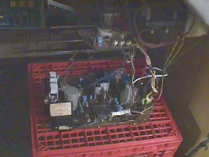
K... below is a pic of the first thing I noticed about John Doe's chassis... got to protect the innocent, you know :-)
K... of course, he could have just blown the fuse for a second time & didn't have a replacement to put in there before sending it to me, but I have seen many come into the shop for repair where the fuse was just fogotten after installing all the caps. Let me add my standard caution here in regards to this fuse being blown.
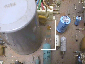
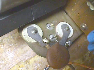
Caution: When removing your G07 chassis from the monitor frame... after discharging the CRT... always take care not to touch the solder side of the chassis until you have a chance to discharge C904... the large gray electrolytic cap to the left of the fuse area above. This capacitor bleeds it charge to circuitry beyond the fuse F901, so when F901 is open the capacitor stays fully armed with a charge that will bite you when you least expect it :-( If you've powered the chassis previous to removing it then the cap has a nice fresh charge on it just waiting for you to provide a path to ground... not that old charges have less bite, but someone may have discharged it previously if it had just been laying around & had not been plugged in. Some caps hold their charge for years, while others dissipate in a matter of weeks, so you just never know what is in store for you, so always discharge this cap. There is quite a snap to this, so you may want to use a resistor to shunt this charge to ground rather then just shorting it to ground. On the frame, this provides a quick way to see if you may need a flyback xformer. If you take a jumper wire & clip one side to ground... while the monitor is unplugged... & dangle the other end down to the fuse end furthest from the back of the chassis & it sparks, chances are good that you'll have to replace the flyback.
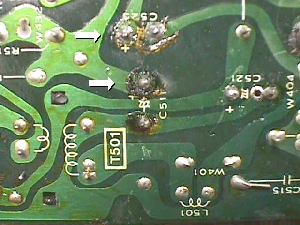
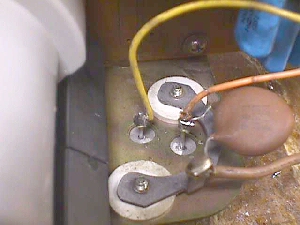
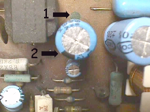 Now... this next pic is to highlight C511 in the center & arrow 1 is pointing to the dark circle on the chassis that indicates the ground side, and it is painfully clear that arrow 2 is pointing to the stripe on the cap that indicates the ground lead side which is 180ş out of sync :-( With the chassis left powered for any length of time this cap will blow open at the relief scores in the top, spewing forth a shower of tin foil bits resembling confetti. Once a cap has been powered up in this manner it is always best to replace it even if it works when you swap it back to it's rightful position.
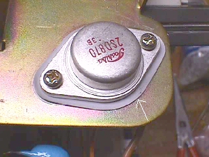
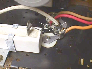
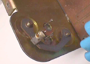 Here's a pic of something I hear people say is impossible to do all the time. I've heard this statement made by some of the best over the years ... "You cannot mount a TO3 transistor backwards!" Wrong... wrong... wrong! Where there's a will, there's a way! I've seen this countless times in the Wells-Gardner K6100 monitors of Tempest fame, as well as, many other brands & apps. I cleared everything away & mounted this TO3 backwards just so you could see what happens when they are mounted backwards. Both the emitter & the base pins are touching the frame & should be right out in the center of the holes when mounted properly.
 The subject chassis is not as bad, but the HOT's collector is shorted to the frame due to poor mounting. The insulators that keep the mounting screws from shorting to the frame were not seated properly allowing the short to occur. The screws actually need to connect the transistor case... the collector... to the isolated retainer where it is then fed to the primary winding of the flyback xformer.
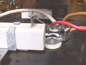
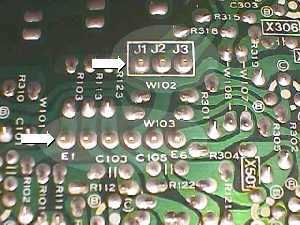 With the pic above I was trying to show solder ringlets on the video & sync headers, but they don't seem to show up well in pics. The 2 headers... 3 position negative sync (top arrow) and the 6 position video & positive sync (lower arrow)... were like baby teeth, loose to the point of almost being able to pluck the headers out with your fingers. Needless to say, this is not good for sync or video & sometimes manifests from one missing color, to several missing colors, to lack of vertical sync or horizontal sync, or any combination of the above. In fact, only one of the two grounds is usually connected, so if it's header pin is broken free from the solder pad you will have nothing on the screen to a negative pic that you cannot sync at all. These headers should be resoldered when you do your cap kit to ensure a good & lasting job. Start at one end of the header & reflow the old solder with new to soften it up & then remove it leaving a nice pretinned pad & pin to solder anew. Step through the rest of the header pins in the same manner, as this goes along rather quickly taking only an added minute to add to the longevity of your chassis.
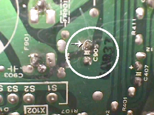 Here is another all too typical problem. C905 above is soldered in, but the pad is torn around the solder & not making connection with the overall pad, making this a small island with paths to nowhere. This is why it is necessary to measure with an ohmmeter from component leg to the next component leg in the same trace to ensure continuity with the rest of the circuit.
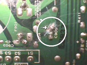 This is how I always repair these... rejoining the island to the mainland. First, it's necessary to scrape the coating off the mainland around the joint to expose the copper trace.
Next tin the area... JIC, tinning is nothing more than applying a minute layer of solder to the surface to aid in bonding the two pieces together. You could just go ahead & solder over this area to join them into one pad, but flexing of the board, aging & other contributing factors may create a cold solder joint & intermittent problem sometime in the future this way, & they are much harder to find, so we don't want that.
This is how I always repair these... rejoining the island to the mainland. First, it's necessary to scrape the coating off the mainland around the joint to expose the copper trace.
Next tin the area... JIC, tinning is nothing more than applying a minute layer of solder to the surface to aid in bonding the two pieces together. You could just go ahead & solder over this area to join them into one pad, but flexing of the board, aging & other contributing factors may create a cold solder joint & intermittent problem sometime in the future this way, & they are much harder to find, so we don't want that.
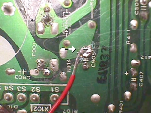 The way that I have found best for a long lasting job is to take a piece of wire, strip back about one inch, tin it, take a small pair of needlenose pliers & form a ring at the end of the wire. Then place this ring over the cap leg & joining the island with the mainland, solder it into place. Snip off the excess wire that you utilized as a handle to keep from burning yourself & you're finished with it :-)
 This poor chassis never stood a chance :-( In the pic above, the top arrow points to C523 which is shorted by small beads of solder in the flux between the terminals of the cap. The lower arrow is pointing to another no connection point on C511... and it is also pretty messy looking... but this is the cap that is in backward & needs to be removed, anyway. Pushing lightly on the top of the cap shows that the leg which appears to be soldered in, moves up & down with the glob of solder staying with the leg... pulling away from the pad :-( This reminds me of another problem I've seen frequently. The replacement caps are soldered in with the body up off the chassis board, i.e., high water installed! I don't know where this comes from, but installed in this fashion leaves an opening for debris to get under the cap & short the legs together & it also provides an easy way to break the cap free of the pads below by any accidental bumping during handling or even later down the road when trying to adjust the monitor.
When you have a real mess from soldering, such as above, you can clean up with household items. Just find an old toothbrush... for that matter, new ones can be bought at the Dollar Store (5/$1), & a bottle of rubbing alcohol. Brush & blot the connections clean & you'll be able to readily spot any potential debris that might short connections.
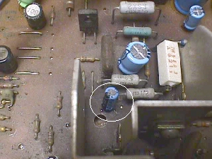 Oh my... I remember very vividly the words, " I've checked my cap orientation over & over again! They are in there the right way!" Oh well... when I flipped this one back over I spotted another in backwards... C408. Here's a tip to spotting these easily when looking at a chassis that someone else has recapped. If you look at my G07 Cap Map you'll notice that a majority of the ground bullets are facing the front of the chassis or toward the flyback. In fact, there are only 4 that deviate from this pattern & 3 of those are under the metal shield out of sight. Knowing this when you look at the chassis makes C408 stand out as it's ground stripe is facing away from the flyback & general population of caps.
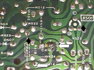 C412 above is also soldered in very poorly & the way that this was determined as a problem was with an ohmmeter as previously stated. Measuring from the positive terminal of the cap to the next component in line... R414... as shown by the white arrows, my meter did not want to zero without a bit of wiggling around of the probes. Cleaning & resoldering straightened this out. Looking at the ground side of the cap you'll see that it has components in either direction from it. Haphazardly checking to only one component may send you into a long period of T-shooting unnecessarily. Always check both ways on a trace for continuity as shown by the black diamonds above for the ground side of C412.
Well... was that all that was wrong with this checked & rechecked chassis? No. One last problem that is shown in the above pic. R517 is shorted to ground! If you look at the lower leg of this resistor you'll see a solder splash that connects it to ground at C412 on the trace. That's all it takes & appearance can be deceiving. You see it & think that it does not touch the adjacent pad... don't believe what you think you see... clear away any solder splashes no matter how harmless they look.
K... before I forget, I mentioned the old plugging in the monitor without an isolation xformer trick & if you're lucky, the only damage you'll have will be one of the bridge rectifiers being blown out or shorted. These diodes are located in positions D901 thru D904. If it got past the bridge, I'd look at the regulator next & beyond that it's a hunt & peck job :-(
I wanted to mention the horizontal width coils here, also. Most are discolored & brittle at this stage... if original... but still usable if they are not broken completely off during the handling of the chassis. Quite often the chassis is placed upside down on the work bench without thought to this coil & it actually stands in for a leg... no pun intended :-)... & it snaps under the pressure. Since the mfr of these coils is up in the air right now, caution should be taken to preserve the one you have. After a couple of price increases on the repros of this coil the mfr decided that it wasn't profitable enough & quit making them, so until someone picks up the slack you should take care with it as though it could not be replaced.
Well... I guess that about covers the things that went wrong during a cap kit installation on this particular chassis, along with some other thoughts that I had, and if any new installation problems arise in the future I'll do my best to get them added here... time permitting. Seems like I only get to play with these pages on holidays :-)
PostScript: I do have one tip I should place here that has helped at least 70 people get their dead G07 back on it's feet when a cap kit & flyback didn't produce a working chassis again, even though the flyback was split open & caps were visibly shot. The tip that saved these from the maul was to remove & check resistor R908, a 47K ohm ˝watt resistor, that often drifts way off value... anywhere from 5K to 500K to open... from the added strain placed on it by the bad flyback, and often times by the shortcutter that jumps his blown F901 with a jumper wire :-( These shortcutters usually end up getting a real surprise the first time a flyback explodes it's body with a sharp earsplitting retort! Sometimes shortcuts come with repercussions :-()
I've taken in a second chassis to see what went wrong & will relate that here hoping it will help others, as well as, guiding another future tech. I guess this one will have to be named Jon Doe to protect the innocent :~)
Overall Jon did a very good job of installing the G07 repair kit & all caps were installed correctly... a few "high-water" jobs, but not too bad... and he had replaced several components that typically do not need replacing, but in this case even the new replacement components were again fried :-(
First quick checks showed these components to be bad including some that he had replaced. The HOT (X01), regulator (X04), xsistor (X901), and resistor (R903) were all toasted & the shorts that caused this were pretty easy to find as they were man-made. The first had to do with the replacement of the HOT. Take a look at the pic below:
K.... so what to heck was crisping everything in the voltage regulator circuit??
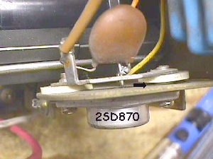
The answer was exactly the same as the HOT, which came as no surprise. If you didn't know to insulate & keep the leads soldered high on the HOT, why would you know to do so on the regulator xsistor. I did grab a pic of this before replacing it, so that you could see how not to do it & it is below:
So... Mission accomplished, how does one do a 24 hour burn-in on this chassis without tying up the jig... providing you have one to begin with ?
All in all... Jon Doe did a decent job & had this page been here already, he'd have done an excellent job... well on his way to techdom :-)