Happy Gaming...........
GO7-CBO Shrunken Pic
by Bob Roberts
The first thing you need to do is install a cap kit because the caps in the horizontal & vertical circuits may have changed value, developed high resistance shorts or simply opened up, and your chances of getting a perfectly formed pic are slim to none.
Once you have installed the cap kit, the next necessary step is to be sure that you have a 120 volt DC B+ power supply to the monitor. If this voltage is low, it will result in a pic termed "postage stamp" which is black on all sides. If it is high, you may be able to shrink the pic to the proper size using other controls, but this higher B+ voltage raises havoc with the rest of the circuitry & will most assuredly cause other premature failures, so it
is important that this be correct from the onset.
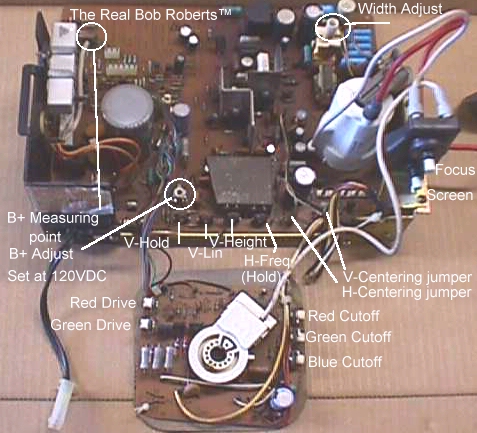
To adjust the B+ for 120 VDC you will need to clip your ground lead of your meter to the metal frame anywhere, and the red lead to the end of R01, the
large white sand resistor mounted on the left side of the chassis frame as in the pic below, on the furthest terminal with the white wire attached to it. If your voltage is off the 120 mark you need to adjust R909 as shown in the pic below, until you have an exact 120 volts DC.
Next locate the jumper wires at the rear right of chassis & labeled H. CENT & V. CENT. With the power off, pull these 2 wires & place them on the center terminals if they are not already there.
NOTE: For the purposes of adjusting you may have to turn your screen control up slightly to define the edges of the pic. When finished, turn back down until background illumination has extinquished into black...just beyond the disappearance of retrace lines in the pic.
Locate the width coil L503 at the front right of the chassis as pic'd below,
and insert a plastic 1/8" hexhead alignment tool into the center. Power up the monitor & using a mirror or sidekick & EXTREME CARE not to get a good shock, adjust the pic until both sides no longer show any black. One side will always fill before the other, so just keep turning until both are just eliminated & not too far off the edge.
Locate V. Height (Size) control approximately center rear of the chassis as pic'd below. Adjust this to show black on the top & bottom of the pic if it is not already black in both places. Now adjust the V. Lin beside that control for an equal amount of black at the top & bottom of the screen.
Once you think you have it equal, go back to V. Height & open it to fill the screen out more. If you see that as you get close to entirely filling the screen, you have a larger amount of black at either top or bottom, simply
go back to the V. Lin & adjust for equal amounts again & then open fully
with the V. Height control.
Yet another project started that I will gradually add to. I'll try to go through all the adjustments, setup, part nomenclature & case histories
of failures, time permitting. For the moment, I'm going to start with
a question that has been asked & answered at least a hundred times in
different variations...
My pic is too small vertically...........
My pic is not wide enough................
My pic is too small all around...........
My pic is too far right..................
My pic is too far left...................
My pic is black at the top...............
My pic is black at the bottom............
My pic is just a square in the center....
Now you can look at your pic checking for centering. If it is too far right or left, up or down, simply move the corresponding jumper wire from step 1 that will put it closer to where you need it. Not an exact science...it is an adjustment that you look for the best possible results & not necessarily perfect results.
If you followed all these steps & still cannot achieve a full pic in some way, you have a component problem in the circuit that is not producing the results you are looking for.
Happy Gaming...........
Help Page Index Big Bear's Bulletin Board Site Index