| I've been waiting to do the Ms Pac-Man rework to show from start to finish on the DC wiring of a cab, but there are just so many new entrants to the hobby that need the help in this basic area that I thought their pleas could wait no longer. I just took one of my basic replacement Jamma harnesses, freshly made, and continued with it by simulating cab installation... as you would upon receiving it... and snapped some pics along the way. |
|
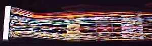
What you'll receive is 54 five foot lengths of wire all pinned & inserted into a Molex 28/56 housing. It is keyed to prevent you from plugging it up to your PCB backwards, ergo 54 wires & not 56, since the key utilizes 2 adjacent positions. The other end of these 54 wires is stripped... prepped for attachment... but totally unterminated. The housing is labeled, so you know what each wire is for. On one end you'll have 12 power wires all to one side of the key. These are 18 gauge wires to easily handle the current flow and are color coded, as well as, being labeled. The black is universally recognized as ground, with red being associated with +5 volts, orange as 12 volts, but the -5 volts is one that is not so agreed upon & consequently may be blue, yellow or brown depending on who's color code is being used. I try to use the color that fits into my overall color scheme when making harnesses, and in this case, for JAMMA, I use yellow 18ga for -5 volts. The remainder of the wires used as I/O are 20 guage. The first thing you need to do with your harness is bundle it. As all of you that have bought my Pac & Galaga harnesses already know, bundling consists of making 6 primary bundles of wires that will stay together to their destination. They are:
|
|
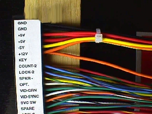
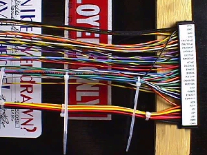
Let's start with those heavier 18 gauge power wires. In the pic above you'll see that I bundled only 11 of the 12 power wires leaving out one 12 volt lead that will be used later. Gather up the 11 wires & cable tie them about 2" to 3" from the housing. From then on you should have a cable tie approximately every 4" or one hand width apart seems to be the easiest way. You don't want to complete your cable tying yet, as you don't know how much of your wire is going to be used in each bundle, nor where your connector breaks are going to fall, so 2 to 3 more cable ties is suffient for now. This should hold the first 12 inches, or so, together & on the very end of the wires you can put a temporary cable tie to keep the wires from straying. Actually, I use wire harness labels to keep them in line & always know what the bundle is for. You could use white tape out on the end & do the same thing by writing the destination on the tape. The pic below is a closeup of the power end & shows the bundle a little more clearly. |
|
Ok... The next one I'm going to tie is the coin door bundle because I am going to utilize that leftout 12 volt wire from the power bundle. It is to supply the 12 volts to the coin door for lamps, meters, bill acceptors, coin lockout coils or whatever accessory you might want to put in your cab. Eleven wires are going into this bundle & I'll briefly mention them & why, if necessary, and I'll put a list afterwards with their harness label position as it reads on the actual housing. The second wire that I'll pick up is ground & I get asked many times about grounds, so I'm going to break this right here & try to clarify the ground issues. [Here goes Bob rambling again] First question in one form or another is "How does the CP ground tie into earth ground?" Well... it doesn't. Having said that, many mfrs did tie their logic ground into earth ground, but it is not necessary & in some cases can present problems that wouldn't have been there save for the tying of the two grounds. What the earth ground is used for is to tie all inert metal parts... casings, bolts, coin doors, framework & such to earth ground... yes... just as you think it is... earth ground as in outside into the ground in your garden :-) This is accomplished by looping all metal together & then into the grounding prong in your AC line input cord, ultimately tying into your power entry box outside your home at which point it runs down to a rod driven into the ground.... hence... earth ground! This is why you always hear people saying to change your AC line cord if someone has cut off the grounding prong on the plug. The link to your garden has obviously been interupted in those cases:-() Logic ground is ground in reference to your DC power source... your 5VDC, 12VDC & -5VDC... whether it comes from a linear power supply, switching supply or plain old battery power! No, it's not like your automobile where any metal surface is actually grounded, so you can't run a wire from your coin door frame up to a switch on your CP looking for logic ground & expect it to close the circuit for you. Just one more seed for this garden before I get back on track. Quite frequently I'm asked how the ground from one end of the Jamma harness is tied to the power supply on the other end & the answer to this CAN be related to your automobile scenario above. The PCBs ground traces are all linked together on both sides of the board, so any place that is designated as ground on the PCB, is just that, logic ground, and unites all logic ground into one common termination back to the supply grounding point at your source of DC power. [Struggling to get back on track] |
|
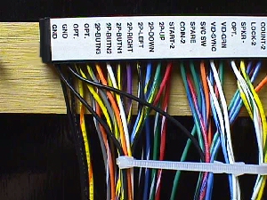
Ok... We have 2 wires in this coin door bundle so far, 12 volts & ground. Next we'll add in the coin counters (meters) for both coin entries, 1 & 2, and also, the lockout coil wires bringing us up to 6 in the bundle at this point. Now I know a lot of you are saying that you have no intentions of hooking up meters or the such, but as I'm sure that you have seen before, just cutting unused wires off or rolling them up in a coil & taping them is just plain ugly! Even though you will not use them at this point in time, you may want to add something in the future, and even if you don't, the way to handle this is to run all wires to your break connector for whatever bundle you are working on and simply let them terminate in that connector. In this case, at the break connector just inside your coin door, you'd only have the wires leading out the connector side to the coin door that you intended to use, i.e., you'd have no wires out of the plug in positions that were not of interest to you. Dead ended, as it were. Neat, but ready for use at a moments notice. Continuing with the coin door bundle, add in the service switch line, test switch line, coin 1 line, coin 2 line & the spare line at position "S" that is sometimes used as a "tilt" line. Let's see... thats 5 lines & 6 above, totaling 11 lines! Coin door bundle finished! |
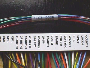
| Snip the cable ties & as you can see in the pic below, I put wire markers out at the end of the wires to keep track of them, but you can mark them however you want, or simply cable tie the end. |
| Bundle three... speaker bundle. Moving right along now :-) The basic need here is only the 2 speaker lines, but the 2 optional lines next to them are sometimes used for stereo, quadraphonic, floor quaking, ear shattering & over the top sound that rocks your house, so we'll carry them along with the speaker wires making for 4 lines in this audio bundle. |
| Halfway there! Time for a video bundle, so that we can see pics on the monitor. This is going to be either 5 or 6 lines depending on the harness you are doing. In the case of JAMMA, it is going to be 5 lines... video red, video green, video blue, video ground & composite sync. Bundle these up in the same manner as the previous bundles. |
| Next is the player bundles & I'll start with player 2 controls so that I end up on the parts side of the connector. You're going to have 11 lines in this bundle...hmmmm.. that sounds familiar. K... we have start, up, down, left, right, & buttons 1 thru 5 along with 1 ground wire to make up this bundle. |
| Time to flip it over & do the last bundle... player 1... and it should be the same as player 2, but wait, 4 times 11 lines is 44 lines, plus 5 video, plus 4 audio only totals to 53 lines & we started with 54. Ah... we have one ground line leftover and what better place to run it than in the player 1 bundle for an extra CP ground wire. All accounted for! |
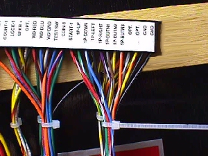
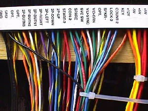
| In the pic below you can see all 6 bundles and the taped player 1 demo about 6" from the end. |
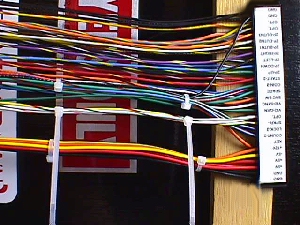
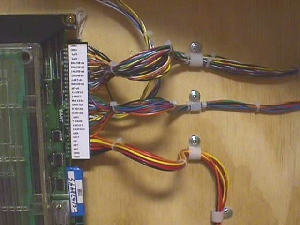
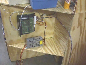
| It's time to start hooking some of this up. I've tacked a game PCB up to start with simulating a left wall mount from the rear of a 2 shelf cab. The speaker & video bundles leave together & go up over the top of the PCB. Next is the 1 & 2 player bundles headed toward the cab front. Then the coin door bundle, also headed toward the front on a little lower path. |
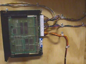
| The bottom bundle is the power bundle headed down for the lower shelf where the PS is mounted. Notice that there is a slack loop in each bundle between the connector & the first cable clamps. This affords plenty of movement when plugging & plugging the Jamma connector. |
|
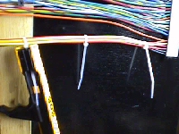
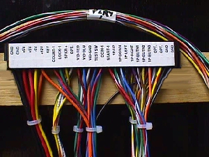
The pic above shows the loops better & also shows how to cinch up the bundles at the cable clamps. Often times you see a game that has had a cable clamp that is too tight for the bundle it is holding & has damaged the insulation, maybe to a point where a couple wires are shorting, even, and this can be eliminated by using a cable clamp that is slightly larger. The reason it was not larger in the first place was that they wanted it to keep the wires in place, but you can accomplish the same thing by putting a cable tie on either side of a clamp that it a little oversized allowing more freedom for the bundle. Below I purposely jumped 2 sizes on the speaker bundle clamp as it headed toward the top of the cab. You can see that even after I cut the cable ties they will be too big to fit though the clamps openings, so they will hold the bundle in place without pinching any wires. |
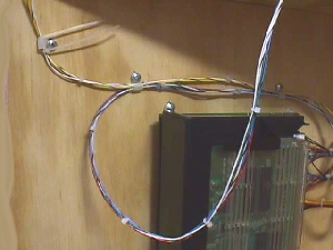
| The video line, above foreground, can either hang loosely, as pic'd, with a cable clamp on the top shelf to keep it in place, or you can cable clamp it up & under the shelf to a convenient place to leave a short loop. Remember that you will no doubt be removing the monitor at some time in the future, so you don't want it to be in the way when unplugged. |
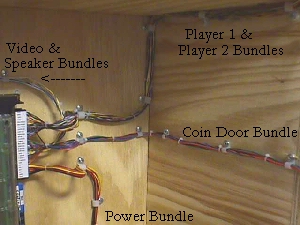
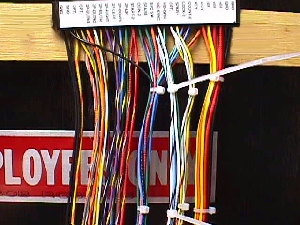
| Okay... I obviously did not cut out a coin door hole in the front for this demo, so I just ran the bundles straight across. They are all labeled in the pic above, as well. |
| The power supply is facing towards the coin door, but it could face towards the back as well, depending on how & where you want it mounted. I always liked to keep the power bundle in as short of a run as possible... 18" to 24" ... to keep line resistance to a minimum. Your power bundle terminates with spade connectors and does not require a break connector, although many mfrs did place one in line just before the PS. It is a little easier in tight spots to unplug & remove the switcher for replacement or repair, say in a countertop game, for instance, but in a roomy upright it's not all that important. Break connectors are important to the CP & coin door, so that they may easily be removed if the need arises. There is no standard connector used among Jamma cabs, but if you are doing a Pac cab or other classic game, you would want to use the same connectors & pinouts, so that you could readily swap out CPs or coin doors from other cabs. You can see that 12 position connectors will handle any of the bundles listed here. I like to put a 2 position Amp break connector in the speaker line to facilitate audio problems that may occur somewhere down the road. It sure is easy to just plug up a new speaker to clear or indict your old one when you have a no sound condition. Incidently, that break connector I put at a convenient spot near the housing, rather than up in the confined speaker compartment. Okay guys & gals, I've got to take another break here as Alice is due home anytime now and the simulated cab that I've been using is her shelf at the end of her counter where she keeps her small plastics bins, and frankly, I wouldn't want to be here if she catches me with that getup still mounted there :-) If I'm fast enough, I'll be right back to type in that label to bundle list I promised. |
|
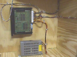
You can see now that cutting out that coin door hole would have landed me in spousal jail :-( I'm back! Made it & if you don't tell Alice, I won't :-) Here's another tip. In the very first paragraph I told you that the ends of the wires were stripped, or prepped, ready for use. I've had this asked a couple of times... If I'm cutting these wires off because they are too long, how does having the ends stripped help me? Let's take the coin door bundle to use as an example. It's going to be fairly short in length, so you'll have quite a bit of wire left. 5 feet of wire is plenty long enough to meet any cab requirements. Let's take the coin door bundle out through the opening by about 6", so that you can easily crimp on the sockets for that half of the break connector. Yes... you will have to prep that as each case is going to be cut at different lengths, but when you go to put the pins on the cut off side to finish wiring out the coin door, you already have those prepped ends to crimp on your pins for the other side of the break connector. Now you can easily match them up color for color & slip them into the connector. Route them to their destinations on the coin door, cut them & attach the appropriate connectors to finish it off. Let's see if I can anticipate any new questions.... well... each line is labeled to their destination, so I guess grounding is the only thing left a little up in the air. You have a ground line coming in with each bundle and in the case of the coin door bundle, you can loop it to every terminal that requires a ground, e.g., you can go to coin switch 1 com, loop up to coin 1 lamp (either side, with 12 volts on the opposing side), then over to coin 2 lamp, down to coin 2 switch com, and if no other grounds are needed, you can close the loop by running back to coin switch 1 com. It'll now take 2 broken wires to kill your coin door ground, but you can omit this last closing lead, if you want. Cp ground is done the same way... Xmas tree light daisy chain style.... at least, the way they use to be. |
BUNDLE PARTS SIDE SOLDER SIDE BUNDLE Power Gnd 1 A
Gnd Power Power Gnd 2 B
Gnd Power Power +5 volts 3 C
+5 volts Power Power +5 volts 4 D
+5 volts Power Power - 5 volts 5 E
-5 volts Power Power +12 volts 6 F
+12 volts Coin Door NA Key 7 H
Key NA Coin Door Count 1 8
J Count 2 Coin Door Coin Door Lock 1 9 K
Lock 2 Coin Door Audio Spkr + 10
L Spkr - Audio Audio Opt. 11 M
Opt. Audio Vid-Sync Vid-red 12 N
Vid-grn Vid-Sync Vid-Sync Vid-blu 13 P
Vid-Sync Vid-Sync Vid-Sync Vid-gnd 14 R
Svc Sw Coin Door Coin Door Test Sw 15 S
Spare Coin Door Coin Door Coin-1 16 T
Coin-2 Coin Door Player 1 Start 1 17 U
Start 2 Player 2 Player 1 1P UP 18 V
2P Up Player 2 Player 1 1P Down 19 W
2P Down Player 2 Player 1 1P Left 20 X
2P Left Player 2 Player 1 1P Right 21 Y
2P Right Player 2 Player 1 1P Butn 1 22 Z
2P Butn 1 Player 2 Player 1 1P Butn 2 23 a
2P Butn 2 Player 2 Player 1 1P Butn 3 24 b
2P Butn 3 Player 2 Player 1 Opt. 25 c
Opt. Player 2 Player 1 Opt. 26 d
Opt. Player 2 Player 1 Gnd 27 e
Gnd Coin Door Player 1 Gnd 28 f
Gnd Player 2