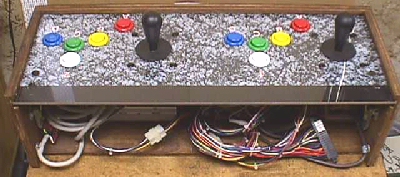
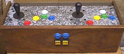
Under the 2 blue buttons mounted on the front are the test & coin up buttons, which are both illuminated to allow the tech to know that the jig is on & hot. Simply unlatching & unplugging the 1 & 2 player harnesses from the CP allows for it's complete removal as pic'd below. In the cabs, this made it very easy for an op to change a game on location in a couple of minutes. Plug up the new JAMMA, or JAMMA adapted board, change the CP to correspond & lock it up, moving on to the next location, which might very well receive the PCB & CP just removed from this cab.
This unit is pretty much self contained with the only missing piece being the monitor. This leaves it open to hookup a monitor that might be sitting on the shelf, floor, in a stationary bench jig or any game that happens to be nearby. I see the fast thinkers wondering how it can hookup to one on the shelf or floor already....don't you need an isolation xformer? Yes! That's why all jigs had them installed whether or not they were to be used at a bench station that already had one.
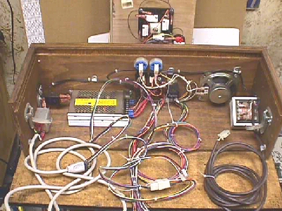
Ok... Let's take a spin around this pic above in a clockwise direction. First we have the 10' AC line cord entering on the left & cable clamped to the sidewall (which easily coils up for storage inside the unit) and it feeds directly into the AC line filter. Exiting from the line filter we enter into a dual purpose push button on/off switch with a self-contained
circuit breaker....no fuse to change here....just push off & on to reset.
Next we see the 15 amp switching power supply...first in the AC line after it has been switched & fused.
Now, right in the center, the end of the JAMMA harness is cable clamped to the bottom & DC power lines run to the switching PS. The CP lines are terminated in player 1 & player 2 receptacles ready to plug in any game CP. Eight to ten inches from the JAMMA edge connector, the video lines are pulled out an terminated in a Molex receptacle allowing for an extension cable to be added to give the video lines about 7 or 8 feet total length to be added to the length of the JAMMA harness, making any monitor easily accessible. At this point, a bullet connector is added across the HS & VS at the Molex extension plug to be capable of shorting the two lines together for any composite sync pcbs that may be connected to it. On the older pcbs with both syncs needed, the bullet only need be unplugged. I suppose a switch could have been used for this, but bullet connectors are much cheaper :)
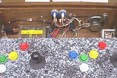
The next thing we see (barely) is a little black box on the front wall which happens to be a coin meter, since this was an important item for an op to have operating properly, it was in all test fixtures. Mounted on the front wall next to it is the speaker & the JAMMA speaker lines simply terminate directly to it with .187 QDs.
Aha....here, mounted on the right sidewall, is the the thing that makes it possible to hookup to monitors on the shelf or floor...the isolation xformer. It is loop fed AC off from the AC line that feeds the power supply, and it has a 10 to 12 foot extension cord leaving the secondary winding. It is cable clamped to the sidewall, and when uncoiled is the means by which a free standing monitor can be powered. The line terminates in an Amp 2 position plug & the reason for this is that the Amp sockets will fit on the Molex power entry pins and the Amp cap pins even though they are "D" polarized.
So we have a test fixture that we can test boards in as well as other things, but how about that monitor that is just sitting around & no one knows, or remembers, if it even works. We seem to be missing something else to test them. How do we produce a video pattern & sync it for this kind of test? Answer: Konami has done that for us.
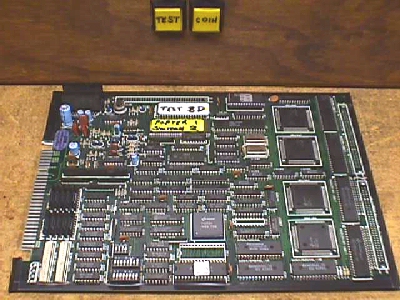
Well..here's the missing part that can generate a test pattern to try out your unknown monitors, or simply work on one sitting on your bench or kitchen table. This is just an old Konami pcb with the dips set to test. Not only can it generate the patterns & color bars for testing/aligning your monitors, it can test the jig I/O & speaker, or it can do all these same things for your JAMMA game cabinet. A piece of cardboard cut to the size of the PCB is taped on all the way around the edge, so that the board can be placed on any surface while it is fired up during the testing.
Well...there you have it. One way to build your own test fixture incorporating all of your own ideas into it.
Happy Gaming........
Help Page Index Big Bear's Bulletin Board Site Index