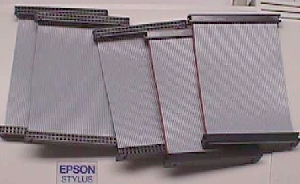
MCR Replacement Ribbon Cables
|
This is one of those things that has been haunting me ever since I said I'd get them made for y'all. I'm going to do my best to cover everything that has come up with these things. As far as I know, these were suggested by Clay Cowgill, at least that was the name that popped up most often in emails. I guess quite a few were attempting to make these things without much success & wanted to know if I could do them or get them ordered in for the Parts Page. I kept saying that I didn't have the time to do anything with them, but as the list of needy people got longer & longer, I caved & sent out RFQs to several companies. I went with the lowest bid on these, but price is the first thing that draws the emails. I know that y'all are emailing about price with good intentions & I thought it would subside, but here we are years later & every newbie that is in someway connected to PCs, sends the email that starts off with you're paying too much for your SCSI cables... you can get them at XYZ for $1 each. Well... yes, I know I can get them under $1 each, but MCR cables cannot exceed 4 inches without added filtering to the lines & these cables are a minimum of 18 inches long! Here are quotes from places that y'all have sent me to because of their inexpensive cables... all well under $2 for 18" cables, at least at the time of these quotes.
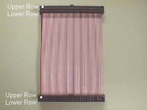
Next is the email stating that there are 2 rows of pins, unlike the originals, and that there are 25 positions in each row instead of 24. Well... when I started with these I didn't think that I needed to go into the mechanics of them as everyone seemed to know how to use them & I remember at the time someone had sent me a link to another Help Page whereby they had doc'd this. I'm guessing this Page is long gone by now & since there are so many new people entering this hobby, I'll try to put a simplified synopsis here.
There are obviously two rows of pins in each connector. You can use either row, but you must use like rows... the 2 upper rows or the 2 lower rows. The 2 upper rows are actually all the odd numbered positions when the connector is used for it's designed purpose and the red stripe on the cable marks the number 1 position as shown in the pic above by the white blocks. It's less confusing if you use this number 1 pin to mate up to your first pin on each header of your MCR PCB and let the last position (49) hang out over the end of the header. Remember... if even one of the five interconnect cables goes from upper on one end to lower on the other, it is the same as not having a cable at all & the game bd will not work. By the same token, if your extra position is on opposite ends it will not work! The extra position hanging over the end has to be hanging over the same end on each connector, so that the end wire of the ribbon goes into space on both ends. Essentially, each cable is it's own 100% plus backup, since you not only have the 2 rows to utilize, you could also use the spare line with either row giving you a little bit more of an edge in case you should somehow damage the outside wire of the ribbon. Another thing that was brought up by James Hagen recently was that the connectors fit tightly up against one side of the PCB when used on Tapper or Timber due to the extra position. I don't have any of the boards here to look at, but I'm guessing this is due to a limited notch space in the PCB. If this is the case, there is almost always an ample distance between the edge of the PCB and any traces or thru holes, so the offending edge can be sanded or filed a tad to make room. Some people are real proficient with Dremels & can burnish down the edge in short order, but I don't recommend that you try this even if you are skilled, because it only takes one slip to ruin a PCB. A piece of sandpaper on a block of wood that fits the opening will easily do the job. You can also use a file, but in both cases, you want to be sure that the solder side of the PCB is fully secured... perhaps on a sheet of cardboard with only the edge you are working on hanging over your bench... and that no residue gets on the parts side of the PCB. Residue from the PCB, eraser residue, if you use one to clean the pins/edge pads on a PCB, should always be kept away from the parts side of a PCB because the particles can work there way into a socket causing a line to be intermittent or totally open. This enlarging is something that was very often necessary on bootleg PCBs & when changing edge connectors as some had ears that were too wide to fit inside the notched out PCB edge fingers. Chopping off the edges of the connector would be an eyesore, whereas shaving a tad off the PCB enlarging the notches was not noticeable at all. As any new questions arise on these interconnect sets I will be sure to address them here. Happy Gaming... |