|
Keeping track of how many games have been played on each of your collection pieces must be the objective lately...2009/2010... as so many have requested info on hooking up coin counters. I'm going to toss up a quick page here in words that even I can understand... non-technical as possible. Let's start with is it a counter or a meter? The two have become synonymous, so much so that even mfrs routinely use both words... sometimes in the sentence. One of you reported that using "counter" on Google would refer you to bulk counters of loose change such as ops used & banks use. I guess that is true, but using "meter" would probably be just as ineffective. From this point on I'm going to refer to it as a counter. Coin counters were obviously used at the onset of game machines to keep an accurate account of coins in the cash box keeping all parties honest. Later on with the advent of electronic bookkeeping many machines dropped the electromechanical counters. It was soon apparent that was an error since a battery was involved along with other components that could fail... hence both were used. Coin counters are available in any one of a dozen operating voltages, but for the most part you'll be dealing with either 5 volt or 12 volt ones. The first thing you need to know is that you'll need a suppression diode referred to as a clamping diode. This is just to block the operating voltage from feeding back to your PCB where it could do some damage. Newer counters will have one internally & will be color coded with one red wire to go to your source voltage & one black wire to your PCB counter output or whatever trigger you are using to pulse the counter. Older counters are likely to have two black wires even though they may still have an internal clamping diode. You can check for diode action with your ohmmeter... flow one way & not the other. If no internal diode is present you'll have to add one externally... banded side to voltage source & other end to PCB. Simplified... the banded side is always hooked to your supply voltage & is just sitting there hot & waiting for a ground pulse to trigger it into action. 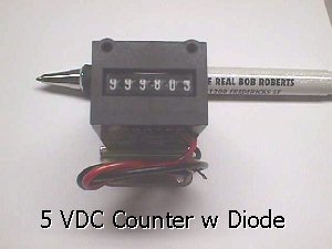 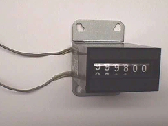 In the two counter versions above you'll notice the top end numbers are shown & this is oftened questioned. The reason for this is allow testing prior to the "000000" starting position permitting easier bookkeeping. Now, as you old hands already know, you can hook these counters up to your coin in lines allowing them to pulse every time a coin passes through the trip wire. You can hook up 2 counters if you have two separate coin in lines or just one counter to keep track of both coin in lines if they are looped together. If you do this you'll need an additional blocking diode when using 12 volt counters. This diode will be in-line with the banded end facing away from the coin in pad on the PCB. This will block the 12 volts from back-feeding to the PCB. If you use both coin 1 & coin 2 input lines with separate counters, or a single counter for both, you'll need a blocking diode on both lines. 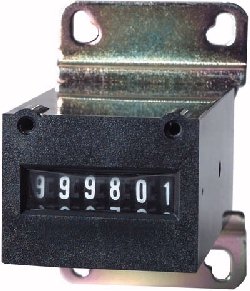 The 5 volt counter above is equipped with two ways of mounting. It can either be mounted using the metal mounting flange on the bottom, or that flange can be removed to allow it to front mount on over/under coin doors using the the two threaded mounting holes on the face. The common 5 volt type (42-2093) with diode & mounting bracket is available on the Parts Page at $5 each if you need replacements. Happy Gaming... |