Using An Ohmmeter
I really didn't want to go here, especially since this is cutting into the time I have to do the Pac wiring that I've been trying to get to for over 5 years, but I've been hearing more & more people ask continuity Qs & then just buy a fistful of components to throw at their problem :-( I guess just from a lack of understanding the basics... and this applies to newbies & old hands alike... so I'm going to throw together a basic oversimplification of how to use an ohmmeter to prove your component to be either good, or bad.
I decided to use one of the little cheapie pocket analog meters from the Parts Page rather than my "expensive" $29 Radio Shack analog meter :-) Over the years I've seen so many people go to measure 120VAC line voltage, without checking to see that their meter was set on ohms, & ka-boom! Some lucky ones only needed to change the meter's fuse, but more often than not, the meter was damaged beyond repair, ergo, I thought the loss of an $8 meter for a newbie would be a bit easier on the game buying capital.
Being from the old school I chose analog because I hate unsoldering parts to check them & digital just doesn't cut it for testing many things in-circuit. Yes... I know digital has taken over the world... TVs, VCRs, radios, clocks, microwaves, automobiles, DVDs... just about everything except Big Ben! Oh, the horror :-( I have a digital remote control for my digital TV which displays the digitalized numerals for the channels & other pertinent info on the screen... which I have to get up & move closer to the screen to read defeating the purpose of my digital remote control :-() Whatever happened to the sun dial? Let me see a hand on a clock face or a needle depicting deflection on my meters :-)
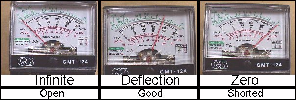
K... let me jump right into this... basically, there are three states to look for:
The "good" above is subjective depending on what you are trying to find out. For instance, I hear many ask how they can tell if their game's line cord is okay & they are hesitant about checking AC voltages & want another way to test it. You can unplug the cord from the wall & measure for a short condition from each prong on the plug to the end of the wire inside the cab. This will help you to identify which color wire is connected to which prong, also. Suppose your earth ground wire was a black or white wire inside the cab instead of the usual green.... when you measure from the tubular ground prong the line that shows the short will be the earth ground wire no matter it's color. This comes in handy when someone has changed the plug on the line cord, or worse, spliced the line cord and you are unsure if it was done correctly :-( Just want to see if the 2 main lines have continuity... clip a jumper wire across the prongs & then just look for a short across your line filter terminals inside the cab. Short indicates good continuity.
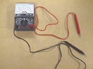
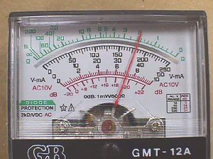
K... here's the little ohmmeter & I'd guess it to be smaller than a pack of cigarettes. It comes with the battery & probes, so it's ready to rock & roll. The positive lead is red & the ground lead is black.
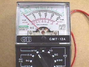
Turn the knob to ohms & we are ready!
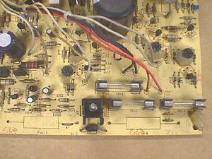
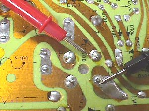
Grabbed this board off the shelf & it has a whole lot of parts that can be tested :-)
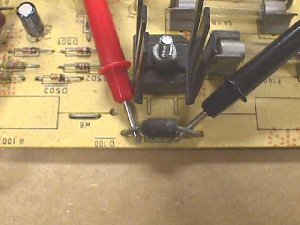
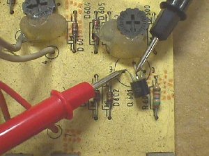
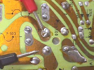
Let's start with this diode. With the red lead on the anode & the black lead on the cathode you should get deflection on the meter as pic'd below. If you reverse the leads it will usually show an open, but in some circuits you may get a minimal feedback reading from other components in the circuit. You need not be concerned with this because if the diode were open you would not get deflection in either direction, and if it were shorted you'd get zero in either direction. This diode is good.
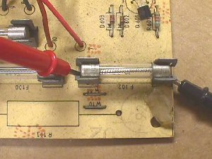
Look at all those fuses. Since we need to see a zero, or short, if these are good, it makes no difference which lead goes where. However, it is best to measure from the base of the fuse holder or even from the solder joints with the board flipped over to insure that you have "good" continuity through the holders, as well.
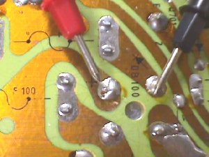
Let's move on to a transistor. This would be like measuring two diodes. You measure from the base (B) to the collector (C) & to the emitter (E). With an NPN transistor you place the black lead on the base & you should have deflection with the red lead on either the collector or emitter.
With a PNP transistor the red lead would be placed on the base & deflection would be read to the collector & the emitter. Knowing what you should get for readings will help you to identify which of the 3 legs on any transistor is the base & whether or not the transistor is an NPN or a PNP type, as well as, letting you know if it is good, or not.
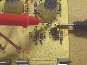
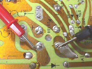
Ocasionally, a transistor will short from collector to emitter, so you should measure between the two as pic'd below. Note that some transistors have an internal dampening diode from collector to emitter, so it is possible to have deflection as long as it does not go to zero.
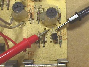
Let's check the bridge rectifier just above the first diode that was tested. The bridge is close to the PCB leaving no room for the probes to touch down, so it has to flipped over & measured from the solder side.
 I think it will help if you see what the inside looks like. This bridge is nothing more than 4 diodes inside arranged in the configuration to the left. The junction where the 2 anodes meet is marked as - and will be ground in your circuit. The junction of the cathodes marked as + will be your DC voltage out. Testing this will be the same as testing 4 diodes even though you cannot see them. Putting the red probe on the terminal marked + you should get meter deflection when the black probe is touched to either AC terminal. One will insure that D1 is okay, while the other will insure that D3 is okay... inside the case.
You test D2 & D4 much the same way, but you need to put the black probe on the terminal marked - and then touchdown on each of the AC terminals with the red probe to view deflection. No matter what the diodes are encased in, they should read the same way. Red probe to the cathode & black probe to the anode will give you deflection & reversing the probes will show an open. Although most failures are shorts, some are opens, so when you don't get a deflection reading that you know is suppose to be there you should reseat the probes & try again & if you still do not get deflection it's time to change the bridge, or single diode, that you are testing.
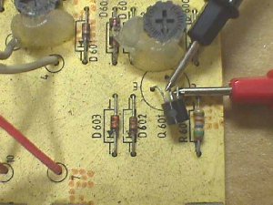
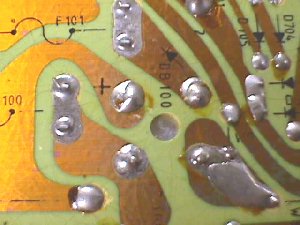
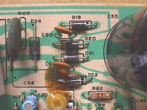
Bridge rectification does not need to be in a single case. Many circuits simply use 4 singles on the PCB as pic'd below on a K7000 chassis. The bridge is comprised of D19, D20, D21, & D22. You can see the junction of the 2 anodes (-) going under the large filter cap & connecting to ground. D19 cathode loops down to D22 cathode to form the + junction.
I have enough of this done to be of help to some, so I'll post it as-is on the Help Page & add to it when I can.