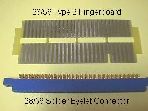
Pac DC Harness To JAMMA Board Adaptor
One of the things I've been doing via email over the years is explaining how to use Ms Pac-Man cabinets to test JAMMA boards. I dread the thought of someone hacking up a Pac cab into a JAMMA, so I've been reluctant to put it up here before now, but there are several people asking how to do this at this time & they want to be able to play the vertically oriented JAMMA bds. Darren of NY was the first to ask me to go through this & I had promised him to map this out for use with an old control panel or a replacement panel set up for JAMMA that could be swapped in & out with the Pac control panel. I've been working at this project for awhile now... 15 minutes here & 30 minutes there... and it's time to post it, keeping my promise.
Let me preface this by saying that this is NOT for a Pac or Ms Pac cab with original wiring utilizing AC power & the on-board DC power supply. This is to be used with a new DC harness or a game that has been converted to a switching power supply.
I'll start with a step by step & y'all can let me know if I wander off course :-)
The basic needs for this project are above if all you intend to do is test Jamma boards to see they have good video & audio. The type 2 fingerboard will have to be cut down to match the 22/44 position harness connector.
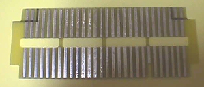 You'll need to cut 2˝ positions from either side on the unkeyed edge & you can mark it out with a felt pen. Although this is not the way I usually do these things, I am going to do this one with basic tools that should be found in any hobbyist garage or tool box. Feel free to improve on this with whatever tools you have on hand.
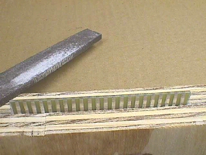
 I placed the fingerbd between two scrap pieces of plywood aligning the marks with the top edge & tightened them into the vise. I figured this would not only protect the fingerbd, but it would also serve as a cutting guide. I did the two vertical cuts first being sure to leave half the trace of the third position on the fingerbd. If this proves to be too wide when you go to insert it into the harness connector, you can take a little more off each end for a proper fit with sandpaper or a file.
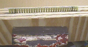
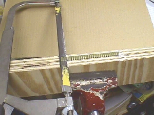 Using the plywood to guide the hacksaw the horizontal cuts were made. Next I tried an old previously cut off Pac edge connector on the fingerbd & found it was a tad too wide for the connector to slip on. I used the file pic'd below to trim up the two sides leaving approximately 1/16" of the trace on both ends. It's important to do this equally to keep the pins in the harness connector perfectly aligned with the pads on the fingerbd.
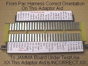
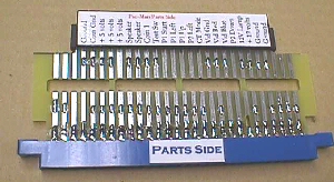
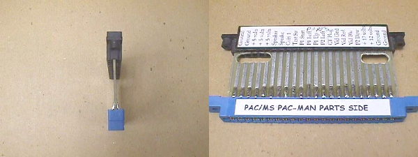
 I placed my adaptor aids on the fingerbd below, but as you can see, the solder side of the JAMMA connection ends up on the wrong side & needs to be flipped 180ş.
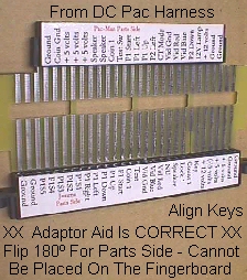
 If you flip it over then both parts sides are on top & your wiring will come out correct.
 I realize that not everyone has my adaptor aids, so I'll tell you how you can get around this the way I use to years ago in the pre-adaptor aid days. You can take white adhesive tape & tape over the connector edges in lieu of the aids & then enlist the boss to hand print each connection on the tape. I say the boss because she'll usually have better printing :-)
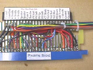
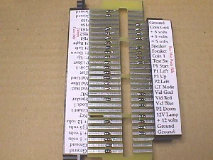 Since not all positions are going to be used on either side of the fingerbd I decided to mark the ones that are used with solder. The Pac harness side will be used anyway, but the JAMMA side connections will go straight to the solder eyelet edge connector, but these little solder markers will not interfere with anything. You may elect not to use them on the JAMMA side if you are confident in your skills.
 Next tack the 28/56 solder eyelet connector onto the JAMMA side of the fingerbd the same way as described in all the adaptor instructions making sure that it is perpendicular as shown on my Pacpower Adaptor Page here. If you are using the adhesive tape to label your connections you won't want to mark this with a "Parts Side" label until you are finished. Also, let me mention :-(before I forget)-: that A: You do not want to leave the adhesive tape on these pieces overnight... the least possible amount of time is best... & B: When you remove the tape you will need to clean wherever you had it with rubbing alcohol to remove any adhesive residue.
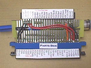 Now it's time to redirect all the power connections from the Pac DC harness input over to the proper JAMMA power inputs using 18 gauge wire. It is best to color code wherever possible.... in this case red for 5VDC, orange for 12VDC & black for ground. After you do the parts side you can flip it over & do the solder side which should mirror the wires on the parts side.
 The other lines that need to be redirected from the Pac DC harness are the video connections, any coin door connections you are using and the speaker connections.... all 20 gauge wire.
 Once all these lines have been redirected and all you want is a simple JAMMA bd tester for basic go/no go conditions... you're finished... label the parts side & you can place the adaptor on a JAMMA bd you want to test & plug it into the Pac DC harness & fire it up.... & if you don't want this to be a literal firing up, make sure you always carefully go over your connections to be sure you rerouted properly.
If you want to utilize this with an interchageable control panel, or if you want to make up a control box to extend your JAMMA testing, you can continue below, where we will be making use of the remainder of my solder markers on the JAMMA side of the adaptor in the pic above.
K.... to pull off this control panel wiring we'll need to go from the solder-marked control panel positions on the fingerbd to the actual controls on the secondary control panel that you are making up in a JAMMA layout... or control box, as both would be treated in the same manner. It's easier to have the lion's share of the wiring with the control panel & a short interconnect harness affixed to the adaptor, so that's the way I will map it out, but you can use connectors on both ends leaving the lion's share of wiring in the cab itself. Of course, you can make it in reverse if you want or be creative in whatever way you want. I'm going to use Amp 9 position connectors, but you can use any brand of connector or one with more positions than just 9 if you want.
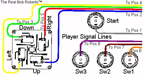
I'm going to assign wire colors now to make the wiring simple & I'll put them in here for you to use if you choose to do so. I'll do this in same-color wiring that can be done with the 10 basic colors & make it very easy for tracing or comparison troubleshooting later on. Every wire color on player 1 controls will correspond with a like color on player 2 controls.
| Bob's JAMMA Control Panel Color Code | |||
| Assigned Wire Color | Amp Position | JAMMA Player 1 | JAMMA Player 2 |
| Gray | 1 Start | 1 Start | |
| Blue | 2 Up | 2 Up | |
| Green | 3 Down | 3 Down | |
| Yellow | 4 Left | 4 Left | |
| Red | 5 Right | 5 Right | |
| Orange | 6 Switch 1 | 6 Switch 1 | |
| Brown | 7 Switch 2 | 7 Switch 2 | |
| Violet | 8 Switch 3 | 8 Switch 3 | |
| Black | 9 Ground | 9 Ground | |
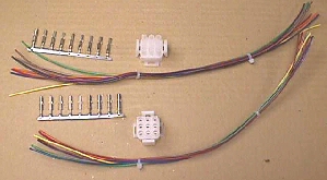 You'll need to cut 2 bundles of the nine colors of 20 ga wire 12 inches in length & cable tie each bundle. Next is to crimp the sockets on one end of each bundle... 18 sockets. Then take the 2 Amp plug halves and insert the proper color wire in each connector position number following the color code chart. You'll find the corresponding numbers stamped on the back side of the plugs... you might need a magnifying glass:-( There is a rib on the exterior of one corner of the connector that signifies position 1 to get you in the right ballpark.
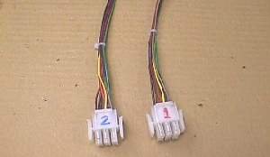 Label one connector #1 & the other #2 & then strip back a quarter inch on each wire in both bundles & tin them with solder in preparation for soldering them to the adaptor on the JAMMA side.
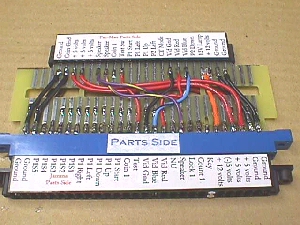
 Solder the #1 control harness to the JAMMA parts side of the adaptor mating colors to pinout following the color code chart. Flip it over & do the same on the solder side for player 2 controls.
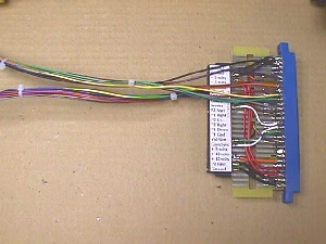
 Now you can put a 90ş bend in the wire just above the soldered connections & head it toward the front of the cab on both sides as pic'd. Cable tie them together after they leave the fingerbd.
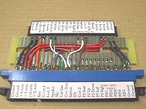
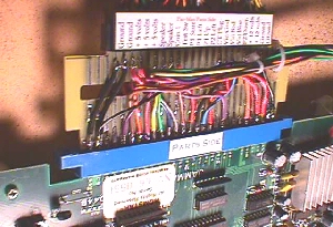
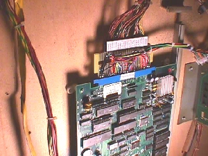 Here's a couple pics of the adaptor on a JAMMA bd sitting in my old clunker Pac cab & you can see that the labeled plugs on the right are ready for mating receptacles/caps from the control panel to be plugged into, routing wiring to proper destinations.
 I don't have the time to do the control panel & snap pics, but there must be a hundred, or so, pages on how to do that up here in netland. Basically, in this case, you'll want to make up 2 more harnesses approximately 3 feet in length using the same 9 colors of wire... this time crimping on the mating pins & inserting them into the proper positions on the mating receptacles/caps following the color code & cable tying them. You can double check by plugging the harness into the adaptor to see that you have the same color going into & out of each position. Remember, this is just a break plug to interupt each line, so they all have to match up when the connector is plugged together. Mark them as before... #1 & #2... and if you are joining the two into one harness to the control panel you'll need to mark the CP end of one bundle with tape (around all 9 wires) & mark with the appropriate number for player 1 or player 2. You can mark both bundles if you are in doubt about anything. This will prevent you from crossing any of your same color wires to the wrong controls.
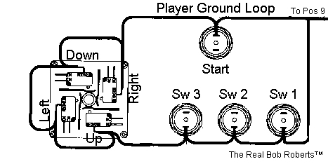
Terminate each bundle into the appropriate player controls with .187 QDs as pic'd below. The player 1 & player 2 should look like twins when both are wired up, so I have only pic'd one side.
I'm going to put together a basic kit for stopping with just a test adaptor & a deluxe kit to include the necessities for hooking up a control panel & I will post both here, as well as, on the Parts Page. Wish I had time to do this in greater detail, but I think these essentials should help you get the project completed.
The basic kit for building a DC Pac harness to JAMMA bd tester will include the following for $8.50.
The deluxe kit for building a DC Pac harness to JAMMA bd with control panel termination will include the following for $17.00.
Just a reminder... this is NOT to be used with the OEM AC Pac/Ms Pac-Man wiring harness. To attempt to do so will feed AC voltages onto whatever JAMMA bd you plug into it rendering it ready for trash pickup :-(