Here is another question that comes up several times per week & answers to it and as much more as I can think of pertaining to this topic. Y'all will have to suffer through some more of my attempts at being a computer artist, as I have sold off all my new game cabs/parts & have no CPs to take actual pics of for illustrations. If I do my usual rambling here, it should give pics time to load up for those with slower modem speeds :şO
Starting with the newbie question... What is JAMMA plus? The answer, at least to my mind, is that it is nothing more than a standard JAMMA game that also has additional headers/connectors for other controls outside the spectrum contained in the main JAMMA edge connector. In other words, it is a JAMMA game or PCB that also has other connections (plus) that require wiring into your cab in order for it to work properly.
Driving games, trackball games & fighting games with more than the typical 3 button per player CP switch configuration are good examples of the JAMMA plus. The JAMMA pinout actually has accommodations for up to 5 buttons per player, but very few games took advantage of that and opted for 3 or less direct JAMMA button inputs, and mounted another header on the PCB for these plus connections, usually in a more convenient spot for the PCB designer.
The driving games & trackball games typically had a 4 or more position .100 spaced in-line header. When this type of unique game specific CP was needed on a universal cab on location, the whole control panel usually went along with the PCB to be changed....sometimes even a wider or deeper CP drawer was used to accommodate such things as having to roll the trackball directly at the monitor glass, giving the player enough room to keep from putting a fist through the glass...and any plus connectors were directly wired to that specific control panel. On the many games that only called for extra buttons for kicks, punches & other various functions, only the PCB & a method to add these input switches from the PCB to the existing CP was necessary. Everyone adopted their own way of accomplishing this, and some manufacturers really came up with some losers...IMHO...requiring free hanging double-sided .100 headers of numerous amounts of positions, and twice as many wires as needed, making the whole system a bird's nest of wiring & an electrical nightmare that even their own techs couldn't keep straight.
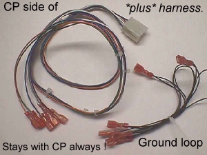
The most common plus harness needed was to control inputs 4, 5 & 6 on the player 1 side of the control panel & the same on the player 2 side. This is only 6 inputs total & a simple feat to add in, but many ops just kept a plus harness right with the PCB that included the ground loops, and whenever they would make a change of games, they would pull the .187 QDs off from the CP switches, more often than not, pulling the wires off & leaving behind the QD still attached to the switch, and many times ending up with ground faults.
The way that I handled this in new games, conversions & multiple game cabs was to first make my own color code for the plus 6 wires, so that they would be universal thoughout all the games that passed through the shop. I'll put the whole thing here with dimemsions & my colors, but if you intend to make up some of these plus harnesses yourself, you can modify any of it to suit your own needs.
| JAMMA Plus Colors | |
| Player 1 Switch 4 | Violet or your color |
| Player 1 Switch 5 | |
| Player 1 Switch 6 | |
| Player 2 Switch 4 | |
| Player 2 Switch 5 | |
| Player 2 Switch 6 | |
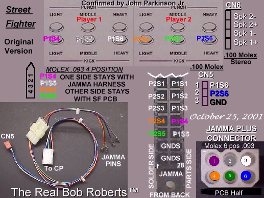
Above are the color codes I've always used and their designated switches on the control panel. Using these colors, I'd cut the first 6 wires 34 inches long...this fit most everything I came across...and crimped on the QDs, cable tied the bundle & added them onto the CP normally open terminals of player 1 switch 4 thru P2S6 as in this great artistry below.
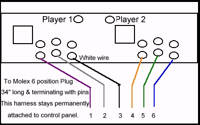
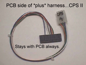
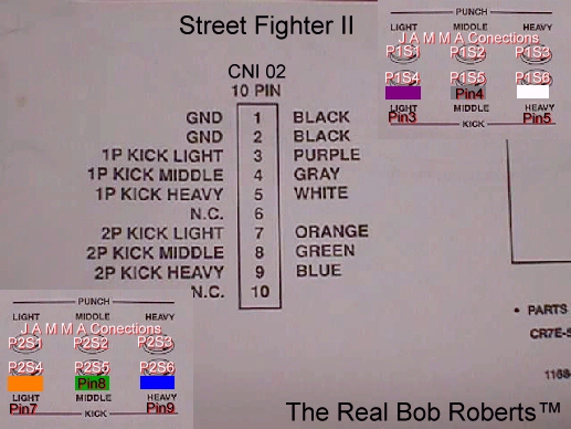
Now it's time to cut the next 6 wires & they are 14 inches in length and will terminate as required by the specific game you wish to control, e.g., Street Fighter II CE would terminate with a .100 Molex 10 position housing at positions 3/4/5 & 7/8/9 of header CNI 02 on the board. This short 14" harness would stay with the PCB at all times, ready to plug up to the plus buttons of any previously wired as above CP.
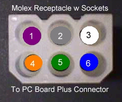
Since we don't want to just twist the ends of these wires together to complete their circuits, I guess it is time we added a Molex .093 6 position plug with pins to the ends of the wires coming from the CP, and to add it's mating Molex .093 receptacle with sockets to the PCB side as pic'd below. Remember now, you want every CP you do to have the Molex plug, and every PCB to have the Molex receptacle. This way they are all interchangable. The connectors are with their respective components, so that when you change out to a different PCB in your cab, you simply plug the 2 together & the JAMMA edge connector for a completely wired game. Just a minute of your time & no cussing at broken or pulled out wires.
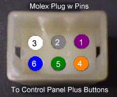

| JAMMA Plus Colors to Molex Pos # | ||
| Player 1 Switch 4 | Violet or your color | 1 |
| Player 1 Switch 5 | 2 | |
| Player 1 Switch 6 | 3 | |
| Player 2 Switch 4 | 4 | |
| Player 2 Switch 5 | 5 | |
| Player 2 Switch 6 | 6 | |
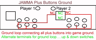
Hmmmm...we now have 6 buttons added to the CP & no way to toggle them to ground. Of course, we could just splice into the ground loop already on the control panel, but there is an easier & neater way to do this. First, let me address the key word above that is often overlooked....that key word being *loop*. When wiring up a control panel's ground circuit, rather than running 2 to 4 wires up to the CP for grounding, it is better to run one...you can have a spare ready to go if you want...and make a continuous & closed loop of it. Done this way, you can cut any one of the ground jumpers and still have a fully functioning ground circuit. Saved many a service call over the years.
Okay... back to the grounding of the plus buttons/switches. You need to cut four 6 inch black wires & 3 12" black wires, get out your QDs and start by putting one on 1 of your 12" wires. Now chain in 2 of the 6" wires... another 12" wire & then two 6" wires, ending up with the final 12" wire, also terminated with a QD. You should have a straight chain when finished that goes like this:
QD-12-QD-6-QD-6-QD-12-QD-6-QD-6-QD-12-QD
JS----COM--COM--COM---COM--COM--COM---JS
LF----SW4---SW5---SW6----SW4--SW5--SW6---RT
To daisy chain the ground loop into the circuit you take one end & plug it to the 2nd player joystick left NC (normally closed) and loop over to P2S6 com, to P2S5 com, to P2S4 com, to P1S6 com, to P1S5 com, to P1S4 com & finally back to joystick 2 right NC. You now have a normally closed ground loop circuit that will always be grounded from one end or the other since you cannot open both left & right switches at the same time. The same will hold true if you use up & down NC switches.
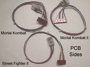
Although I don't have pics of the CPs, I do have pics of the harnesses as sold on the Parts Page, and I can put them up here for *my pic is worth a thousand words* illustration. As you can see from the pics below, this will save you money if you only have a Mortal Kombat & a spare MK II PCB that you swap out in the same cab....now for the collector who has five or more different plus PCBs that are utilized in the same cab, a big savings is seen, since after the main harness is installed, each game PCB only needs the short side...cheaper to build, or cheaper to buy at $7.50. For that matter, buying the 2 piece harness at $15 is less than the sometimes $25 for a game specific plus harness from the manufacturer.
Much easier to understand this concept with pics, huh? I could have typed in another thousand words, but I'll spare you :)
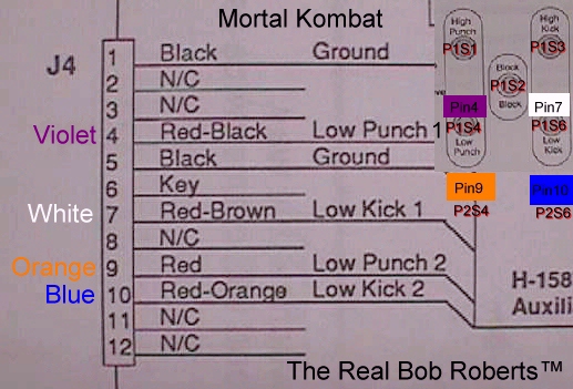
Here's a few common layout maps:
This is a little off from this old guy's forte, but I'll give it a stab... A couple of people have asked about these plus harnesses as it pertains to using a PC to run lots of games in a single cab. Obviously, these would be 180ş out from what would be needed for that purpose, but their goals seem to be the same....keep the game cab intact to revert back to OEM with no hacks such as cutting off the PCB plus connector & soldering the wires directly back to the PC keyboard I/O, so the above concept should aid in that endeavor, also. You can (A) replace the game plus harness to one of this type & then get a PCB side open ended for connecting to the keyboard I/O...1 plug & you are back to OEM, or (B) cut the existing OEM harness in this same manner, installing a Molex connector in line and then make up your own PCB side Molex with the other end connecting up to your keyboard I/O. CP switches then toggle either the OEM PCB, or if plugged to the PC, the representative keystoke.
As always, all these parts can be found on the Parts Page .
Happy Gaming..............
Help Page Index Big Bear's Bulletin Board Site Index