|
SIPs are nothing more than a network of resistors in one package. There are numerous types of cases including the chip array that looks like a simple IC, a surface mount similar to an IC with it's leads flared out to the sides like wings, but the most common one that we deal with in the classic game boards is the in-line through-hole SIP (Single Inline Package).
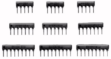 I'm going to just generalize here & cut to the chase as quick as I can. There are quite a few sub-types to this through-hole SIP type such as the series type: 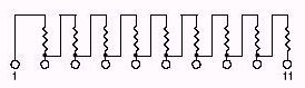 The isolated type: 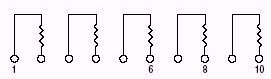 There are others like the ladder type and combinations with caps to produce RC networks, but the most common type to vids is the bussed resistor network. 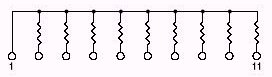 These are used as pull up or pull down resistors, so the lead marked with a dot on most, and a 1 or indented circle on others, will mark the common lead to each resistor. With some of the imports I've noticed that just a stripe is used or they just cram the identifying lettering to the end signifying the number 1 pin. Of course, if there are no pointers at all to the number one pin you can always use an ohmmeter to locate the common end. Whatever the value of the SIP is will be measured the same to each pin from the common #1 end pin. Measuring from the wrong end will result in a doubling of the value to the next pin because you will be reading 2 resisitors in series with each other. 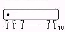 This array of bussed resistors typically come in 4,6,8,9,10 & 11 pin packages. If you order an 11 package what you'll have is 10 resistors because the number 1 pin is the common for each resistor. It's helpful when looking for these when it is fully spelled out for you, e.g., 11 Pin SIP 10 Resistor Bussed Network, but I find that is seldom the case. They expect you will know what you need & it often times leads to order errors. 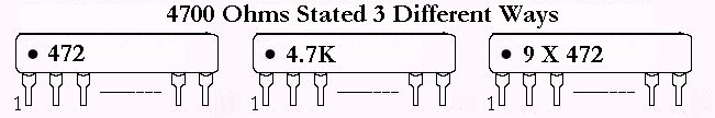 When it comes to the value of each resistor in the network it can get confusing by the way it is stated on the component. Many have long part numbers on them that hide the value within them. Some use typical resistor written code expressing the value, while others clearly stamp the value directly on them. If you are not familiar with reading resistor shorthand you can get a general idea on the Trimmer Pot Page. Remember, if all else fails you can always use your ohmmeter to come up with the value... it'll be the lesser value of the two measured from from either end to a middle pin. Let's see that one... has to be less confusing:
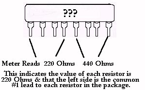 Here's a tip: If you are measuring one to replace the above example and you read 660 ohms in place of the 440 ohms in the pic, you've got the wrong type of SIP because you are actually reading three resistors in a series network. Okay... these are important to the classic boards for a couple reasons & why I'm taking the time to do this. First is that they often get mishandled & broken. Secondly, with so many used as pull up/pull down resistor banks, they frequently are the cause of inoperative controls. Whenever you see these SIPs you should carefully inspect them... perhaps even using a magnifying glass... to be sure that they have no hairline cracks in the encasement. If you have a control panel switch that is dead & it has a SIP used as a pull up, you can use your meter to see if a voltage equal to other operating pushbutton switches is present on the offending switch. If it is not present, and after confirming wiring to be good, you can trace back to the one resistor associated with the offender in the SIP & if it still is missing ... with other pins measuring correctly... then you need to replace that SIP. Now that I've outlined a brief basic idea of what these SIPs do for us, I'll toss in a couple cheats here that you may want to use when you get stuck with the age old problem of not being able to find the correct component that you need. For instance, in the last paragraph, when you find one resistor in the package is open, you can get a single resistor of the same value as the open one & bridge it in from pin 1 common to the dead output pin lead.... effectively replacing the dead soldier within the fortress. You do not necessarily have to be on the pins themselves as you can tie to other solder points that are directly connected to the pins you need to use for bridging. A second cheat is a little more dependent on your skills & requires a Dremel type tool. It does the trick without looking too ugly, in fact, a daub of Magic Marker for the finish product usually makes it undetectable by most, unless pointed out.
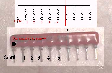 Let's say you require a SIP with a bank of 5 x 1K resistors plus the common for a total of 6 pins. You search the world over for one, but all you can find is a 1K SIP with a bank of 9 x 1K... as pic'd above. You only need 5 resistors & you have 9, so you simply go to resistor 6, pin 7, don your goggles & use your Dremel to cut right down the center of resistor 6. This will eliminate the unwanted resistors while making sure that resistor 5 does not get damaged. Note that the numbers pic'd indicate the resistors & not actual pinout. You can cut closer to resistor 5 if the footprint you are working with requires it. If your footprint is unchallenged on the PCB, you can simply cut the unwanted pins/legs from the SIP & install it complete without any fancy Dremel work. K... here's a last resort cheat that many like even better. I've been sending the pic below out for many years now & it is finally time for it to be where all can see it... crappy as it is, the point always seems to get across right away. It's not a finish product, but rather one that illustrates the concept better. I'm really glad to get to this point as I have been working on this page for nearly 2 years time.. you know, not full time, 5 minutes one week & 10 minutes a month later trying to figure out what you were trying to convey in the last 5 minutes spent on it & what was done with the pics, and of course, adding another 5 minutes to it. Suffice it to say that this is one of a hundred started that is nearly done... phew! :-) Yes... the pic is coming :-) 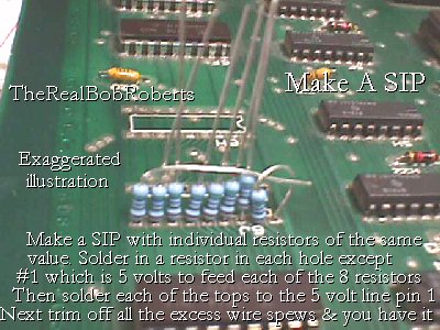 We still have a few odds & ends of SIPs on the Parts Page and since there are so few, I'll go ahead & make a table of them here. |