For beginners (newbies) the best way to change this speed-up chip is to remove the pcb.
These directions are for the Ms Pac-Man upright (UR) machine, the most detailed and the others can be done easily by modifying these instructions.
1. Remove the hex-head screws holding the plastic pcb mounts to the cabinet on the side closest to the back door & the short piece from the top, closest to the back door. The board will readily slide out now after unplugging the harness and taking note of it's direction....so that you do not reinstall it backward, you may want to put a piece of tape on the side facing you....but before you slide it out you need to remove the auxillary board from it's metal holder.
2. To remove the auxillary board, you will notice 4 plastic prongs, 1 in each corner of the pcb. You need to pinch the plastic lock in the center of each one of prongs with a pair of needle-nose pliers and gently pull the pcb corner toward you. After doing all 4 the pcb will be free and you will be able to slide the main pcb from it's holder.
3. You probably don't have a work bench, so you will need to put several layers of newspaper on whichever table your spouse will allow you to use. The component nubs on the solder side of the pcb are very sharp and will scratch you and the table, the reason for the newspaper.
4. 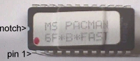 It is best to lay it out with the ribbon & auxillary board facing you. In this manner
you will notice that all the IC chips on the pcb & it's plug in satellite boards now
have the small notch in the end all pointed to your left. These chips must always have
their notches pointing in this direction regardless of any writing on the chips. Some
chips will have the writing, especially if someone has replaced them before, upside
down so you must follow closely the direction of the notches. Failure to do so, will
result in a defective or blown chip at the very least.
It is best to lay it out with the ribbon & auxillary board facing you. In this manner
you will notice that all the IC chips on the pcb & it's plug in satellite boards now
have the small notch in the end all pointed to your left. These chips must always have
their notches pointing in this direction regardless of any writing on the chips. Some
chips will have the writing, especially if someone has replaced them before, upside
down so you must follow closely the direction of the notches. Failure to do so, will
result in a defective or blown chip at the very least.
5. 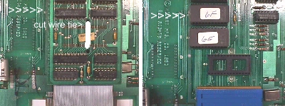 The speed-up chip you want to install is under the small satellite board closest to
the ribbon cable. There are 4 roms or eproms there marked on the board on the
notch side as 6E/6F/6H/6J. The one you will need to replace is 6F. First, you will
probably need to cut the wire tie that is holding the small satellite board in place.
The speed-up chip you want to install is under the small satellite board closest to
the ribbon cable. There are 4 roms or eproms there marked on the board on the
notch side as 6E/6F/6H/6J. The one you will need to replace is 6F. First, you will
probably need to cut the wire tie that is holding the small satellite board in place.
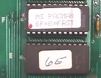
6. Remove the small satellite board from it's socket by gently prying upward on one end and then the other, until it is free. So you will have no doubts, this board has on the notch side (to the left) the writing *Z-80 sync buss controller (285).
7. Using a small screwdriver gently pry between the socket and the chip 6F first on one end and then the other, back & forth until it has been raised from it's socket. You do not want to try to completely remove the chip with one try as you will bend all the pins on the other end of it. You also, do not want to shove the screwdriver way in under the chip & pry as you will scratch the traces (trails) on the main pcb.
8.  Now you are ready to install the new speed-up chip 6F. Make sure it is facing with
the notch to the left and line up the pins on the side furthest away from you and just
barely into the socket. Next you can line up the pins closest to you and as you are
gently pushing the chip into the socket, you may have to exert a minimal force toward
the back of the board so that the pins will go in place freely. You want to be careful
not to bend a pin underneath the socket where it will not make connection or have a pin
on the outside of the socket & not making connection.
Now you are ready to install the new speed-up chip 6F. Make sure it is facing with
the notch to the left and line up the pins on the side furthest away from you and just
barely into the socket. Next you can line up the pins closest to you and as you are
gently pushing the chip into the socket, you may have to exert a minimal force toward
the back of the board so that the pins will go in place freely. You want to be careful
not to bend a pin underneath the socket where it will not make connection or have a pin
on the outside of the socket & not making connection.
9. Ok...your new speed-up chip is installed. Now the process reverses. Put the small satellite board (Z-80 sync controller) back in it's socket much the same way. Make sure the notches/writing on board are to the left and line up the back pins with the socket and in this case the front pins should pretty much fall into place so you just have to make sure it is in there securely.
10. Slide your pcb back into the cabinet and hang your auxillary board by the top 2 prongs loosely or snapping one into place. Reconnect the wiring harness and power up your game to see that all went smoothly before securing the pcbs permanently.
Note: The rom letters that corespond to positions are as follows:
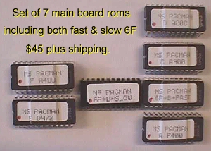 A = 6E
B = 6F
C = 6H
D = 6J
E = 5E
F = 5F
Happy Gaming...........
Roms-Proms-Eproms can be found on the "Parts Page"
All the help you will need with Pac games
can be found here:

Help Page Index Big Bear's Bulletin Board Site Index