
Super Pac-Man To Jamma
Foreword: Aloha Steve.... Well, I thought everyone would be able to wire up a straight forward reroute of wiring for the Super Pac-Man to Jamma Adaptor, but someone has finally had a problem doing this, so to aid anyone else that is attempting to make one of these adaptors I'm going to put my notes up here along with a few pics. Happy Gaming all....
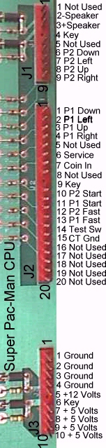
SPM pinout rerouted to Jamma. This can be set up in cocktail table mode by grounding J2P15, so both 1 & 2 players need to be wired, and a bullet connector placed in the ground line that goes from J2P15 to Jamma ground. Unplug the bullet for upright games & plug it together for cocktail table operation to flip the pic.
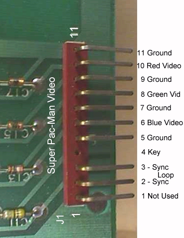
To reduce resistance, use 3 of the 4 grounds on the video board at J1P5/7/9/11 split up to return to 3 of the 4 double Jamma ground pads on the fingerboard and use the 4th for the Jamma video ground. Use 18ga wire for all 4 +5 volt terminals at CPU J3P7/8/9/10 back to the fingerboard, as well as, for all the grounds to the fingerboard.
Coin 1 in at CPU J2P7 can simply loop from Jamma coin 1 in to Jamma coin 2 in, or you can run coin 2 over to coin 2 on the SPM side at J2P8.
Wouch! Too much typing, or thinking, or both, & I've got a headache now, so I hope this proves useful to at least one other person. I put the JAMMA pinout hugging the centerline with the SPM pinout in the outer columns.
I find this way of mapping to be very helpful to people who are not use to following industry maps, i.e., the electronically challenged :)
That's about all I can think of, so I'll put the finish product below.
Here's another pic I found of a completed one... more of a side view.
As always, all the parts you need can be found on the Parts Page.
Addendum: Okay... so you want to play SP-M for free, huh? Yes, we can do this the somewhat more labor conscious way without touching the cab by means of the adaptor card. All you need do is run a jumper wire through a bullet connector from JAMMA "T" to "U" to accomplish this feat. When you want it to be in the free play mode simply plug the bullet together allowing for you to push the 2-player start button to coin up a game for one player, or pushing it twice will send you into a 2-player free play game.
Want to be able to control this option easily? Mount a simple on/off switch via an easily removed cable tie to the harness just inside the coin door and
run a pair of wires from it to the adaptor. Now using bullet connectors simply plug onto the ones on the adaptor to extend this feature out to the easily accessed coin door. This will allow you to make any adaptors you want utilizing this feature with remote control, while still being self-sufficient if used in a cab without this provision. I would use a wire color different than that of the CT jumper wire with bullet plug to keep from cross connecting the two. Red should stop any thinking person from mating one of these to the black CT jumpers :) Universal 5 volt color to universal ground color always makes a person stop to ponder a bit... granted not long enough in some cases, but here no permanent damage can be done, anyway.
Of course, you could use a 2 or 3 position Molex connector to accomplish this quick disconnect & use a separate jumper plug when a cab switch is not available, but I have found that these have a tendency to get lost... even when I have tethered them to the adaptor card:( Anyway... this is just a simple wiring wizardry to mimic what I have been saying to do to the cabs for years now, making it into a free play mode machine. Of course, if you are not a purist, you can simply install this on the cab side permanently
to switch in & out of 2-player free play mode. Note: Yes... I said purist..
remember that not so long ago ops were gutting out what make you cringe now, so I expect by the time JAMMA 3 is in place, these Jamma cabs will be the "OMG, you didn't do that" cab of the day...classic! This would save you from individual adaptor wiring on a continual basis, but be advised that some game boards will not function in this mode. Some IOs will detect this as a short, i.e., a closed switch, while others will see it as a tilt & shut down the CPU. You would have to flip the switch to the open position whenever you encountered one of these in order for the CPU to operate. When you have a game board that has the free play option via IO, I'm still in favor of using this method over the dip switch method because I find that using the dips will eventually burn a pattern into the CRT's phosphor... sometimes very quickly if the CRT drives are set higher than they need to be.
Help Page Index Big Bear's Bulletin Board
Site Index
The Real Bob Roberts™
PARTS SIDE SOLDER SIDE CPU J3P1 Ground 1 A
Ground Video J1P11 CPU J3P2 Ground 2 B
Ground Video J1P9 CPU J3P7 +5 volts 3 C
+5 volts CPU J3P8 CPU J3P9 +5 volts 4 D
+5 volts CPU J3P10 NU - 5 volts 5 E
-5 volts NU CPU J3P5 +12 volts 6 F
+12 volts CPU J3P5 NA Key 7 H
Key NA NU Coin Counter 1 8
J Coin Counter 2 NU NU Coin Lockout 9 K
Coin Lockout NU CPU J1P3 Speaker + 10
L Speaker - CPU J1P2 NU Not Used 11 M
Not Used NU Video J1P10 Red Video 12 N
Green Video Video J1P8 Video J1P6 Blue Video 13 P
Composite Sync Video J1P2&3 Video J1P5 Video Ground 14 R
Service Switch CPU J2P6 CPU J2P14 Test 15 S
Tilt NU CPU J2P7 P1 Coin 16 T
P2 Coin CPU J2P7/8 CPU J2P11 P1 Start 17 U
P2 Start CPU J2P10 CPU J2P3 P1 UP 18 V
P2 Up CPU J1P8 CPU J2P1 P1 Down 19 W
P2 Down CPU J1P6 CPU J2P2 P1 Left 20 X
P2 Left CPU J1P7 CPU J2P4 P1 Right 21 Y
P2 Right CPU J1P9 CPU J2P13 P1 Button 1 22 Z
P2 Button 1 CPU J2P12 NU P1 Button 2 23 a
P2 Button 2 NU NU P1 Button 3 24 b
P2 Button 3 NU NU P1 Button 4 25 c
P2 Button 4 NU NU P1 Button 5 26 d
P2 button 5 NU CPU J3P3 Ground 27 e
Ground Video J1P7 CPU J2P15 NO Ground 28 f
Ground CPU J3P4 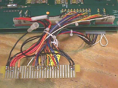

Happy Gaming...........