Another troublesome & *confusing* thing for newbies seems to be trackballs. At first I wondered how this could be, but as I started experimenting with the various aspects of this common dilema, I soon found myself wondering about how all these differences are going to be kept straight. Happs' tech, Danny Wong, had told me that any mods they did conformed to the original trackballs & I took it for gospel until Sunshine (Elio), brought up the fact he was having trouble with a replacement wiring harness not wanting to work properly.
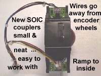
Well, I talked to Danny again & he reassured me that the harness was the same & that I shouldn't have to reverse clk & dir on them as I suggested. In fact, he said if I had to, then they must have gotten a bad batch of harnesses. Maybe so, but from the tests I ran & Elio's input, as well as, input from Scott C. King, I've come to the conclusion that in changing over to SOIC chip & reversing the friction locks on the headers...a very good idea...causes some changes in wiring to be necessary.
I'll start off with the modifications that we made in the field back in the 1980s to preface this a bit.
 The OEM installation of the trackball units put the horizontal optical coupling
pcb at the very back with the control panel open, and very hard to get at for service...
nearly impossible on the Centipede...no room for big hands back there at all. Well,
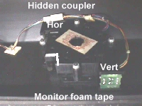
the mod that I used came from an idea that one of my ops gave me. I'd rotate them
90ş & swap the plugs on the 2 coupler pcbs, essentially swapping the chores of the 2 boards.
The OEM installation of the trackball units put the horizontal optical coupling
pcb at the very back with the control panel open, and very hard to get at for service...
nearly impossible on the Centipede...no room for big hands back there at all. Well,
the mod that I used came from an idea that one of my ops gave me. I'd rotate them
90ş & swap the plugs on the 2 coupler pcbs, essentially swapping the chores of the 2 boards.
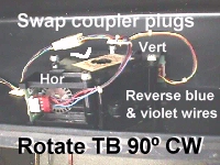
 The horizontal now became the vertical & vice versa. This exposed both couplers to the open area of the control panel. One more thing was needed, however.
The vertical still operated correctly, but the horizontal tracked in the opposite direction of ball roll.....kind of fun to try to remember to roll the opposite way from what you wanted while playing the games, but.....it needed to be fixed & the fix is to simply swap the blue wire in the header plug with the violet wire to change direction of roll to match the ball travel. Easily accomplished since MTAs were used. All you needed to do was pull the wire out & move it to the other end & push it back in with a jeweler's screwdriver, while off the header, of course.
The horizontal now became the vertical & vice versa. This exposed both couplers to the open area of the control panel. One more thing was needed, however.
The vertical still operated correctly, but the horizontal tracked in the opposite direction of ball roll.....kind of fun to try to remember to roll the opposite way from what you wanted while playing the games, but.....it needed to be fixed & the fix is to simply swap the blue wire in the header plug with the violet wire to change direction of roll to match the ball travel. Easily accomplished since MTAs were used. All you needed to do was pull the wire out & move it to the other end & push it back in with a jeweler's screwdriver, while off the header, of course.
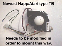 Moving up to 1999, I find that the new trackball units are being shipped out with the same type modified orientation, even with arrows on them to show direction of mount,
however, they did not reverse the blue & violet wires in the harness, so it plugs up
from the box with the horizontal tracking in the reverse direction. This is using the
assembly with harness straight from the box & mounting as directed. I'd say the best course of action would be to swap the 2 wires, so that the optic encoder pcbs are out in the open area now.....a much better place for them as far as I'm concerned.
Moving up to 1999, I find that the new trackball units are being shipped out with the same type modified orientation, even with arrows on them to show direction of mount,
however, they did not reverse the blue & violet wires in the harness, so it plugs up
from the box with the horizontal tracking in the reverse direction. This is using the
assembly with harness straight from the box & mounting as directed. I'd say the best course of action would be to swap the 2 wires, so that the optic encoder pcbs are out in the open area now.....a much better place for them as far as I'm concerned.
 Of course, you can elect to take the easy way out & just swap the 2 plugs & disregard the arrow & mount the trackball in the original conventional manner. Now all things should work fine, providing you keep the same optic boards & harness....changing either will have an adverse effect which will require you to do some type of modification. Throughout all of these tests I performed, the one constant in all situations was the ground & 5 volts always remained the same, no matter what. It is possible
to insert the plugs backward to the locking ramps, though, so care should be taken to see that they are not & that they are not sitting over 1 pin to the right or left on the header.
Of course, you can elect to take the easy way out & just swap the 2 plugs & disregard the arrow & mount the trackball in the original conventional manner. Now all things should work fine, providing you keep the same optic boards & harness....changing either will have an adverse effect which will require you to do some type of modification. Throughout all of these tests I performed, the one constant in all situations was the ground & 5 volts always remained the same, no matter what. It is possible
to insert the plugs backward to the locking ramps, though, so care should be taken to see that they are not & that they are not sitting over 1 pin to the right or left on the header.
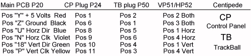
Before going on, let me map out the circuit's path for wiring from the main pcb to the optic pcb using a Centipede as a guide since most are the same basic wiring, just starting from different main pcb edge connector pins.
Now I'll go into some of the test results when different variations of harnesses & optic pcbs were installed in Centipede, Millipede & Marble Madness.
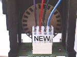 In the pic on the left is an original TB with harness showing the horizontal pcb connection and on the right is that same pic with a new 1999 harness attached. As you can readily see, the dir & clk are reversed & the wires are still going inward toward the encoder wheel, and you will have to swap the
2 outside wires in order to keep the TB configuration the same. If a new optic pcb were installed, the wiring would be right & would exit the side away from the encoder wheel since the ramps are reversed on them.
In the pic on the left is an original TB with harness showing the horizontal pcb connection and on the right is that same pic with a new 1999 harness attached. As you can readily see, the dir & clk are reversed & the wires are still going inward toward the encoder wheel, and you will have to swap the
2 outside wires in order to keep the TB configuration the same. If a new optic pcb were installed, the wiring would be right & would exit the side away from the encoder wheel since the ramps are reversed on them.
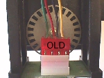
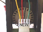 The same thing holds true on the vertical pcb connections as you can see the old trackball with pcb and wiring on the left looks much the same as the horizontal wiring did. In looking at the pic on the right that has the new 1999 harness attached, we see that the outside wires used for clk and dir are reversed once again. If you were to change one of the optic pcbs to the newer type, the wiring would be correct in this conventional mounting using the new harness, but the old pcb remaining would need to have the outside wires swapped.
Basically, if the combination of new & old optic pcbs along with new or old wiring harnesses are not giving you the proper direction of travel, you only need to swap outer wires to change direction and you never want to try to swap the red & black wires or insert the connector backward.
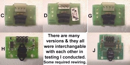
Here's a look at the evolution of the TB optic boards that I have at my disposal, albeit incomplete, which are also used in steering wheels & other encoding devices.
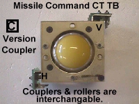
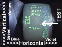 On the left is a pic of a 2Ľ" trackball unit used in the Missile Command cocktail table(CT) and the new TB roller sets will fit right in these with an idler shaft leftover. The complete TB kit($21) will also replace the
bearings with a spare bearing left, as well. On the right is a screen shot of the test mode screen depicting travel & color code for the horizontal & vertical optic pcbs' wiring to give you an idea of which set of wires need to be swapped to effect a correctly operating TB.
On the left is a pic of a 2Ľ" trackball unit used in the Missile Command cocktail table(CT) and the new TB roller sets will fit right in these with an idler shaft leftover. The complete TB kit($21) will also replace the
bearings with a spare bearing left, as well. On the right is a screen shot of the test mode screen depicting travel & color code for the horizontal & vertical optic pcbs' wiring to give you an idea of which set of wires need to be swapped to effect a correctly operating TB.
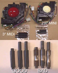
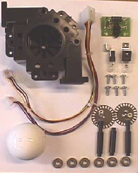 On the left is pic'd the mini 2Ľ" trackball & the 3" midi trackball. At the bottom of the pic is a set of worn roller & idler shafts along side a new set. As you can see the ball will drop into the case pretty deep when the
shafts are worn. On the right are all the parts used in the trackball from
the plastic housing to the screws that hold it together to encoder wheels. The lamp sockets are for illumination of the 3" translucent balls which many have used in place of the solid color balls for the effect it gives to the CP.
On the left is pic'd the mini 2Ľ" trackball & the 3" midi trackball. At the bottom of the pic is a set of worn roller & idler shafts along side a new set. As you can see the ball will drop into the case pretty deep when the
shafts are worn. On the right are all the parts used in the trackball from
the plastic housing to the screws that hold it together to encoder wheels. The lamp sockets are for illumination of the 3" translucent balls which many have used in place of the solid color balls for the effect it gives to the CP.
Update: May 27, 2001
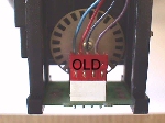
After much confusion, Happ went back to the conventional mounting method with the arrows made into the plastic cases. Installed this way, your green & yellow wired plug should go onto the optic bd right under the imprint of the arrow & word *monitor* on the case.
If you use a new wire harness with the old optic bds, you'll have to reverse the 2 outside wires...clock & direction...but with the new optic bds... rev "H", the harness is right since the headers are facing in the opposite direction. The new harnesses also use REAL Molex connectors rather than the MTA push in wires... solved a lot of intermittent problems.
As always, all these parts including new & used trackball assemblies can be found on the the Parts Page .
Happy Gaming........
Help Page Index Big Bear's Bulletin Board Site Index