For quick video t-shooting in the shop, I use this simple to build device which can aid in checking a variety of components on the pc board right on your work bench. The one I have is made up on a 9-pin Molex plug because all my jigs are made compatible with these for quick coupling of any device. You can make it up using a Molex in-line header & housing, enabling you to insert it in line with a video game monitor right in the cabinet, if you so desire.
The basics of this device are that you can control the video on the screen. You can turn any or all colors off going to the CRT. The first step is to interupt the video feed lines... R-G-B...by making an interupt cable of your choosing, to insert in line. You can get as elaborate or as simple as you want.
An elaborate one would be in a case with the connectors mounted, as well as, the cutoff switches and even a banana jack to insert the probe, with the adjustment pot also mounted in the case.
My simple design is quickest to build & use and is based on free-hanging the components. I used an old coin window plexi...because it was handy...& mounted the 3 mini-switches on it. Next I got a Molex 9-position plug & receptacle and ran the sync & ground straight through and the R-G-B signals were run to the in/out terminals of the mini-switches. At this point, I am able to turn any of the 3 video signals on or off.
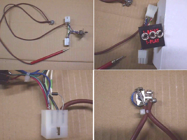
Now, how to use this to T-shoot? I took a test lead, & since I wanted this free
hanging, I cut it about a foot from the probe & inserted a 5k ohm thumbwheel pot.
Now I am able to adjust the input from the probe by changing the resistance in the
input line. Next, this input has to be fed somewhere. In my Molex 9-position, I
am only using 6 of the positions, so I opted to connect a blocking diode in line,
by pinning the anode & the input lead together & inserting them into a dummy
position for added strength. The cathode of the diode was then pinned to the
blue input....cause I like blue...for an input that could be seen on the CRT.
Ready to work! Once you have this in line to your test monitor, you can cut off
the RGB inputs and the screen will go blank. At this point, any feed from the
probe will show up directly on the monitor. For instance, if you probe the outputs
of a 74LS161...11/12/13/14...you should see a pattern and it should step up
with each pin of the output. If you hit on the 5 volts, your screen color will turn on.
If you hit on ground, nothing will happen. You can turn on the R &/or G video feeds
while probing, as well, if it helps you to compare. After using this method of
T-shooting, you will become familiar with different patterns, and know right away
when something is amiss.
Happy Gaming...............
Help Page Index Big Bear's Bulletin Board Site Index