Although there are several FAQs about the converting of a Williams linear power supply to a switching power supply, I am still asked about the lamp circuit frequently after the installation of one my plug-n-play conversion kits.
I glanced through a couple of the FAQs & saw that they recommended doing something that I would not do personally, so I thought I would add my version & the reasoning behind my choices here.
They recommend removing the wires from the AC transformer supply for the coin door lamps & running one to ground and the other to either the -5 volts or +12 volts on the switcher [1813 lamps must be used for 12 volts] and both did not mention fusing this line, which theoretically is acceptable since the switcher will have short protection 99% of the time. Now if you have a cab with no original transformer or linear power supply installed, I guess I would be forced to go along with this method, with the addition of new lamp sockets that were well insulated, but should you have the original transformer installed in the cab, I would recommend using it.
Why? My first thought is because it is there, but secondarily I look at the failures that occur when the short protection circuits are over used, and then I look at a known failure of the WMs coin door lamp holders... as they age the terminals tend to spin & short to one another... and I have to think that it is much more prudent to change a fuse rather than a switcher, or at a minimum removing & repairing it (time consuming).
Yes... I know the critics will say you have short protection, why not use it? My best analogy would be that you all have emergency brakes on your automobiles, but would you choose to use them instead of your foot brakes? I'm no auto mechanic, but I don't think this would be a good practice. The short protection circuit is there to protect you from that once in a lifetime... hopefully... mysterious short that arises & not for encore performances on a regular basis caused by faulty lamp holders.
I would much rather keep the isolated & fused AC supply from the transformer feeding these coin door lamps... the only reason for the existence of this xformer winding:( Ok... so you don't have the original power supply in the cab... where the fuse holder was so wisely mounted for the coin door lamps :( Well move it! Not literally... just install another fuse holder in the cab bottom, or use an in-line fuse holder with the wires already attached for you, to relocate the fuse & holder to a more suitable home.
Note: A very common mistake that lots of people make is always blaming the transformer for voltage problems. The reason for this is because usually the common meter lead is put on ground in the cab to take measurements to the terminals & then compare to voltages on the schematic. News flash.... AC (alternating current) is not measured from ground as DC voltages are, but rather between the 2 terminals of the winding being measured & with the meter set to AC voltage... not DC voltage. [Not sarcasm...impact :)]
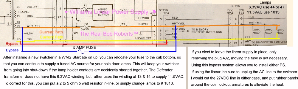
That said, the pic below shows the AC path from the transformer to the lamps, and only the lamps.... the sole purpose for this winding... via the yellow line & the orange line. You'll note that the yellow line simply enters one side of the original power supply & goes directly across the pcb to the opposite side where it continues on to one side of the lamps. The orange line makes one brief stop to go through a fuse holder & then continues on to the opposite side of the lamps thus feeding 6.3VAC to each of the lamps. The red & blue lines show how to bypass the OEM PS & feed the coin door lamps with the PS removed from circuit. You can solder the bypass wires to the transformer at the numbered & color coded positions & line tap them beyond connector 4P3 as indicated. You could join the wires to the terminals of that connector if you have some new .156 terminals. Don't forget.. the blue line has to go through the added fuse holder.
Note: Some Williams' games route the control panel ground &/or coin door ground through the memory protect ground return which makes physical ground through the header 4J3 on the linear power supply, and in these cases, if the linear is removed from the cabinet, then you will have to physically tie the ground loop to a known good ground line. Barring all else, you can run a new ground line all the way back to the switcher's spare ground terminal, or simply run a jumper from the spare ground terminal to 4P3P6 on the removed plug.
Tip: The pasted together diagram above should also answer another common Q... Why does the 5 amp fuse F2 keep blowing out on my power supply? Well.... from this you can see that it only fuses the coin door lamps, hence if it continually blows you have either the dreaded lamp holder/s shorting their terminals together, or you have a wire shorting to the metal someplace... usually around the coin door hinge where it can be pinched & nicked when closing the door.
FAQ
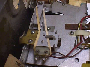
> I have the *silver* coin door on my Defender with one lockout coil that activates a rod that controls all three coin mech lockouts. How do I use a rubber band on this?
While on the subject of the Williams power supplies I may as well express my humble opinions about them, once more, as it has been a few years since my postings to the newsgroups and there are many newbies to the hobby now. As most of you avid collectors know already, I think that these are a great linear power supply & have always repaired them even when installing a switcher, having the best of both worlds. I've heard the complaint about how the power supply ate up your rams... yes they are extremely power sensitive utilizing 3 different voltages... but... what is forgotten is the fact that these supplies were work horses for 20 years with little or no maintenance to speak of! If the game was working & taking in those quarters for it's owner, then there was no need for servicing them, right?? Well.. as a result of this lack of attention over decades, the headers are often broken free from their pads causing an intermittent delivery of power to the boards. This periodicity of power being applied to the boards is what damages (eats up)your rams... not anything that the power supply is to blame for, & had it had some preventative maintenance over it's lifetime, it would still be ticking strong.
It looks like some 500, or so, linears have been restored to good health over the past 4 years with my rebuild kits, but as I'm typing this, I am thinking about redoing it to include the pot that I installed on all of mine to adjust the 5 volts. I did this because ops continued to, and still do, use these linears to power later games through Jamma to date. When putting together kits for repairing them, I didn't think this would be necessary for use in the cabinets as designed for, but in this millennium we have seen the desire to run multi-games in Williams cabinets, so I think it prudent to include the pot & instructions along with the 4P1 Molex connector that so often burns up as a result of these ringed header pins. Most kits were accompanied by WMs OEM PS connector kits, but I think that if the 4P1 were part of the repair kit it would save you from having to do the others in most cases, and although it would cost slightly more, the savings from having to buy a connector kit will more than make up the difference.
I will try to find the time to document the addition of a pot to control the 5 volts with pics here.... perhaps on the next holiday :) I'm reminded of a recent email about the kits & I'll post it here along with my answer as it may help others. Edited, of course, to protect the innocent:)
Q. I have a question for you. I just installed one of your Wms OEM PS Connector & Repair Kits in a Defender and am experiencing a problem that I have not seen before in a Williams game. Please do not think this email is a complaint in any way but rather I am trying to understand what is going on as I have installed your kit before, several times, and this is the first time I have seen this.
Sym. First off I have checked all the voltages after installing the kit and they are right where they should be. Now the problem I am experiencing is a horizontal hum bar from top to bottom when the game is powered up. From there I get the normal rug pattern then a Ram Error and the machine reboots. If I swap in a known working power board, the hum bar goes away and the game plays normal. Any ideas?
A. Check list:
1 I know you didn't install anything backwards so goto 2 :)
2 Check all installed component spews (ends you cut) to make sure
they have continuity from them to the next component in all directions.
Looking for an open from pad to trace.
3 Carefully look the board over for solder spills/splashes that may
be shorting two points that should not be.
4 Carefully examine all header pins not only for good pad to pin
connections, but also connector pin to header pin, as sometimes
the header pins will have a bit of corrosion on one that is hard to
see, but which prevents a stable connection.
5 Maybe time to go back to your day job if you started with a
working board :( [said jokingly]
If I had to guess in the blind... I'd say you have a bad connection
at the 2N3055.
Reply. Your guess was correct. The 2N3055 was not seated
properly underneath the heat sink.
Note: This is a very common problem with TO3 (bottlecap) transistors in monitors, power supplies & other PC boards & is due to the fact that the collector gets it's connection through the mounting screws. Always be sure that they are tightened down securely.
Happy Gaming...........
Help Page Index Big Bear's Bulletin Board Site Index