I've heard over & over again, statements made about crimp connecting to the effect of, "I just can't do them right", " the pins fall off after I crimp them", "they are not as good as soldered on" & an assortment of others. This is my feeble attempt to inform people on the proper crimpers to use & the use of them, at least the way I use them, anyway. I'll use the Molex split pin for an example. This is a pin designed for a Molex single or double sided .156" (3,96mm) edge connector and is actually a bifurcated contact terminal in the proper terminology....pin is much easier.
 Pics
Pics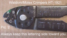
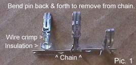
The pins, as pictured above, are gold & nickel plated at the wire crimp (conductor tab) for a better connection on this brass based pin. The insulation crimp (tab) will hold up to two 18 gauge stranded wires.
In the second picture (Pic. 2) above is the best all-in-one coin-op crimpers ever made, IMHO. I don't like using them as the instructions suggest & watched every new employee fumble with them following their instructions, and found them & myself, too slow in getting the job done the way they describe. Their picture also seems to be a view in which you are facing the person using them, which adds further confusion, so I will explain this my way rather than from their instructions.
The first thing I do with a new pair of crimpers is paint the top edge green or red,
with the tool facing me so that I can read the engravings on it. No matter how busy
I am, or who I'm talking to at the time I pick up the crimpers, my eye catches that
painted surface and guides me to having them in the proper position without a single
hesitation....right side up & the correct side facing me. You might have noticed the
small drip of green paint running over the top edge by the "A" in Pic. 2 on my set
above. On employees sets, I also painted a thin line of silver paint straight down the
center of the anvils at "A" & "B" in the picture, so that they would crimp down in the
proper places.
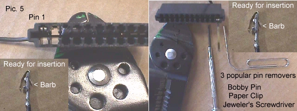
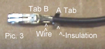
Now we are ready to use them & the *come with* instructions say to strip back the insulation on the wire about 3/16" which is what I do (Pic. 3). In the next step, they say to load a pin into the anvil & hold it in place with the crimpers while sliding the wire in. This is too slow for a hobbyist, let alone someone trying to make a living with tools, so I do just the opposite......I load the pin onto the stripped wire, which I have to hold anyway, so holding the end of the pin to the wire at the insulation tab is a quick & easy way to accomplish 2 things at once. Now my right hand is free to use the crimpers & position them where they are needed.
 Pics
Pics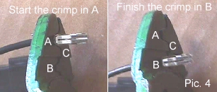
Some tabs are flared out quite a bit on pins, so I start the wire tabs in "A" anvil so that they begin the turn inward before I put them in the "B" anvil (wire crimp anvil) for their finishing touches as depicted in the picture on the right above. I also do this with the insulation tabs, but you shouldn't bare down too hard in the "B" anvil as you can pinch out an excess unwanted protrusion that will prevent you from inserting the pin easily. If this should happen, you can reposition the crimpers & crimp it back into place.