
In order to help more than one person at a time, I thought I would put my notes here on repeat requests. Maybe a one line answer or perhaps one of my novelettes... whatever happens to be called for at the moment. Since I lack the time to keep banging out html pages, I thought I would just scroll them in as they pop up in hodgepodge fashion as it takes very little time to move text to this format.
|
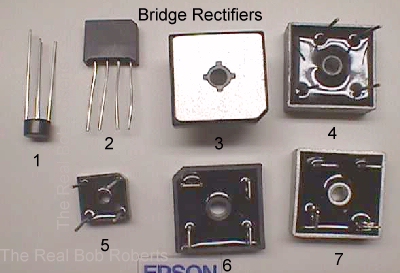
XY B&W Deflection Board Bridge Here's a typical email pertaining to the bridge: > I need to replace a bridge rectifier that came out of my Asteroids. > The part number is KBPC602. On the side opposite of the part number it has 7924. > I saw this KBPC-601 Bridge Rectifier 6A 100V Pic 5 $1.50 > Can you tell me if they're interchangeable?
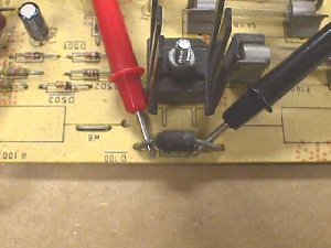 The bridge in the pic is just above the diode under test. The key to reading bridges is in there part number. I've mapped out others onsite in various places, but I'll do this one right here separately.
The 602 = 62 = 6 amp 200 volts.
The 601 = 61 = 6 amp 100 volts.
The 604 = 64 = 6 amp 400 volts. So... which one do you pick from the Parts Page?
The answer would be: I dropped the BR62 in favor of the BR64 to cover the most bridges requested with one stocking part. As for the last part of the email: 7924 = 1979 week 24 the date it was born :-) One final thing while here... many hobbyist request 8 amp bridges when replacing this one. There is no advantage to doing this that I can see & I wanted to point out that the physical size of the 8 amp bridge is larger & has larger leads, both of which make for a tiresome & ugly replacement in MHO.
|
|
Quick Note On The .156 Extractor! The .156 pin extractor, aka JAMMA pin extractor, cannot be used to pry with.... as many have found out the hard way, including myself back in the day. I think I bought one with every order I ever placed with the "real" Wico. 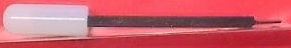 You can see that the tip is very small, thin & not made for prying no matter how tempting. Usually the reason one is tempted to pry is due to the dog being hung up on the housing. The way to avoid this is to push the wire into the connector as though inserting it for the first time, while sliding the extractor in the opposite side. Then when you pull the wire & pin out of the housing it will glide right over the extractor preventing hang ups & practically falling out. Should you break the tip off it is not hopeless... you can make a new tip with a grinding wheel. If you've bent the dog over on a pin & cannot get it out of the housing a precision screwdriver or a bobby pin can sometimes force it out. |
|
FAQ - Do the B+ filters come in the cap kits? No. There are no kits on the market that I'm aware of that come with B+ filters. This would make any kit cost prohibitive unnecessarily. Typically, a bad filter is going to give you a shrunken pic with the hula... maybe large black bars going thru the pic & possibly even a humming or buzzing will be heard. If you have one of those symptoms or just want to refresh your existing one you can purchase it separately. |
|
FAQ - Xreference for parts on the Zenith built K7000?
Flyback - None |
|
FAQ - Do you have a replacement flyback for a WG K4600, K4700, K4800, K4900, K5500 or K5600? No. This series of flybacks was so strong that no replacements were warranted. Only in recent years have they started giving up the ghost & at this juncture I would guess a person would go broke in repro'g them for the few that have died. |
|
Frequently Heard - My HOT is shorted out according to my DMM. You cannot measure a HOT in or out of circuit with a DMM if it has an internal damper. Many without a damper cannot be measured without removing at least one leg from the circuit. That's why no one has ever been able to pry my analog meter from my hands. I hate having to unsolder a component just to test it only to solder it back again after it proves to be okay. The reason for this when there is no internal damper present is from an external component bridging two of the legs... commonly a coil or flyback winding. 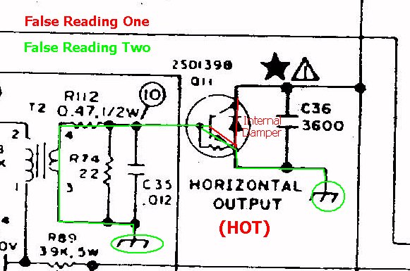 Many HOTs have an internal resistor, such as the one above, making it even a little more complicated when it comes to measuring it. While here in the HOT seat another thing that seems to be a reoccurring theme is not putting the mica insulator back when replacing the HOT. The HOT has to be insulated from the framework or heatsink. When you remove the old HOT the insulator may be still stuck to it. Usually it has enough heat sink compound still on it to reuse it with the new HOT, but you can always put a new one with new heat sink compound on the replacement for a fresh start. Some of the newer chassis' use a completely encapsulated in plastic case preventing the collector from shorting to the framework, but if you have one that the metal tab is exposed on you'll need to use a plastic screw, or at least a plastic insert with a metal screw, to prevent shorting. One other thing comes to mind.... over the past couple years I've had a dozen, or so, of the guys tell me that they've had trouble with heatsink compound that they've purchased from local stores being conductive. In each case the compound had to be removed & HOT replaced. The mount had to be cleaned with alcohol & allowed to thoroughly dry before replacing the mica & "good" compound for the new HOT. At least two reported seeing blue sparks dancing on the compound to the frame like leaky spark plug wires in an automobile. My guess is that this is probably something sold by a large nationwide electronics store to effect such a diverse number of states. Update: |
|
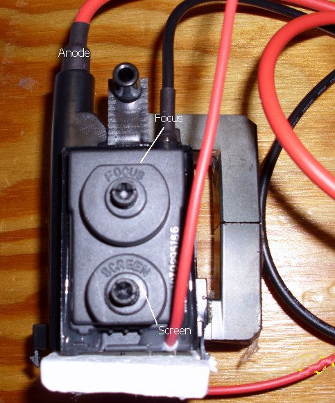
FAQ - Which wire goes where on the replacement flyback transformer? It doesn't matter what color the wires are. The 40KV heaviest wire with the suction cup connector on it goes to the anode on the CRT. The 20KV wire, next heaviest, goes to the focus pin of the neck board socket that plugs up to the CRT pins. That only leaves the lightest wire... usually 2KV... and it goes to the screen voltage post on the neck board. Actually, on most flybacks the screen voltage wire exits the casing right at the screen control, while the focus wire exits at the focus control.
 |
FAQ - Where do I hook-up the wire for the common terminals of my microswitches?
With an influx of newbies to the collecting world come some of the most
basic questions that we all take for granted.
The answer should be self-evident on my Help Page
here:
Basically, you run a ground line from your edge connector ground & loop all
the commons into it & then back to your starting point, attaching it to an
adjacent ground position in the edge connector, so that if one connection to
ground fails the other will keep the integrity of the ground circuit. You
can also terminate your loop for each line that you run since it would be
obvious as to the location of an open ground line by the area in which your
switches do not function. For example, I always run a separate ground line
for each of the following areas...
Wiring other that the 18ga power conductors should be done with 20ga
whenever possible & 22ga when you just don't have the 20ga that you need.
Anything smaller than that is just a pain to work with & maintain. It might
be fine for your thermostat wire in the attic of your home, or in the phone
lines in your wall or any other app where the wiring is not exposed to us
humans & has screw terminals for termination of that smaller wire, but right
out here in the real world where we have to come in contact with this wire &
utilize it for crimping, soldering or even the el cheapo push-in
connectors... it just doesn't wash :-( Cabs used to swap in & out multiple
PCBs don't stand a chance with the smaller gauge wires considering the
amount of times they must be handled. The only thing I could think of that
could be worse, would be using solid wire in place of stranded wire in game
use :-( Now that's not asking for trouble, it's begging for trouble :-()
Replacement Jamma harnesses in their infancy tried to skimp on wire gauges &
brought barrels of grief to buyers & techs alike. Wires pulling right out of
the connector housing.... overheating power terminals... burning edge
pads... having to crank the switcher open to full bore in order to bus the 5
volts to the components on the PCB... intermittent connections..... open
connections where the insulation actually fooled you into believing that the
wire was still connected by hanging onto the terminal saddle... and a parcel
of other misadventures along the way to destinations via intra-cabinet break
connectors.... CP, coin door, video & etc. To add ease to the demise of a
connection, quite often the paws of even this *Big Bear* would sometimes
snag a wire and yank it from it's home while removing or installing some
component :-(
Symptom:
No movement up or down!
Power off... remove optic connector with blue & violet wires for clock and
direction and let it hang free. Now take the optic connector with green &
yellow wires & move it to the now empty optic bd connector. Power on ...
move trackball for left & right movement.
Results:
A. You can move up & down now by rolling the ball side to side.
Examine the first optic bd for a cold or open solder joint & replace if it
appears to be okay as you most likely have a bad optic sensor.
B. You still cannot move in any direction.
You need to examine the connectors & wiring all the way back to the main PCB
edge connector. If you find no breaks/opens in the wiring then chances are
that you have a problem on board.
No movement left or right!
Power off... remove optic connector with green & yellow wires for clock and
direction and let it hang free. Now take the optic connector with blue &
violet wires & move it to the now empty optic bd connector. Power on ...
move trackball for up & down movement.
Results:
A. You can move side to side now by rolling the ball up & down.
Examine the first optic bd for a cold or open solder joint & replace if it
appears to be okay as you most likely have a bad optic sensor.
B. You still cannot move in any direction.
You need to examine the connectors & wiring all the way back to the main PCB
edge connector. If you find no breaks/opens in the wiring then chances are
that you have a problem on board.
Happy Gaming.......
This one has been topping the charts for quite sometime, so it's earned a spot up here.
Well... this is how I do it... right or wrong! First you disassemble the unit & since you only want to be toting the case bottom around for modification, I'd suggest you leave the harness on the optic bds with the case top in the positions they go in. This should be of help when you go to put it back together, physically noting where they belong, preventing you from mixing up vertical & horizontal wiring.
Next would be to wash up the bottom case with dish soap & warm water, rinse & dry, & you're ready to drill. The center hole needs to be enlarged to 3/8" to allow enough light through. I use a step drill for this, but I imagine you could use a std 3/8" bit utilizing the existing hole as a pilot. Now take your lamp/lamp holder & align it over the hole. If you align the filament inside the bulb with the center of the hole it'll give you a more uniform look. Keeping this alignment you can pivot the holder to a good location for fastening. If you are going to drill a pilot hole make sure that it will not interfere with any necessary components on the inside, e.g., don't drill the hole where the screw will go right up through under a bearing :-( I always chose not to drill the pilot, but to use one of the slots to either side of the case for fastening. The screw makes it's own threads as it goes. I've never cracked a case... hmmm, sounds like something that Perry Mason would never say :-)... in doing it this way, but I have wondered if things were going to go smoothly many times. I was afraid it would crack the first time I tried this on an old broken case, but that was not the case, proving once again that you just never know till you try something new.
K.... reassemble the TB unit & mount it back just the way you found it!!
Note: DO NOT overtighten the screws that hold the case together! They only need to be snugged up hand tight & trying to reef them will destroy them now, or later.
Now we need some power to illuminate this lamp. If you take a couple pieces of 20ga wire, 1 black for ground & 1 orange for 10-12VDC, about 10" long, you can fasten them in no particular polarity, across the 2 terminals of the lamp holder. Add a Molex 2 position connector to the other end & then cable tie it to the TB harness. This keeps it contained with less risk of it getting entangled in the moving parts of the TB. Note: If you decide to use a 6 volt lamp you can swap in a red 20ga wire for the orange above. Keeping power lines color coded is not only neat & useful, but it might save you, or some tech in the future, a whole lot of guess work.
Now you'll have to continue your wiring from the other side of your newly installed connector to whatever power source you have selected. I recommend that the 5VDC logic lines not be tapped into.
Why add the extra load when you have such a vast selection of sources at hand. To keep lines to a minimum in most cabs you have your control panel & coin door break connectors in the same general area, if not side by side, making it easy to tap into coin door power lines. Obviously, your black ground wire can tap in anyplace that has a logic ground line passing by.
As for the orange wire, most coin doors have a drop for 10 to 12VDC to provide power for coin lockouts, if used. Sometimes the coin meters are driven by 12VDC, also.
Oh... for the red wire people that are thinking if they can't use the 5VDC logic power, where do they derive their power from... many coin doors have 6.3VAC power available for coin rejector illumination, whether or not it is used, it can usually be found in the coin door break plug... cab side only if not already in use. Always consult your game's manual to see what power is available to you in your particular cab.
Of course, if this is going into a cab of your own design, you can provide the power directly from your power supply up to the area of your control panel. You'll still need to use a break connector just prior to the TB.
Ready to smoke test it.... good luck & Happy Gaming....
PostScript: I mentioned that I used a broken case to experiment with years ago, and I should mention how many of these cases were prematurely sent to the junk pile :-( It seems ops.... and now hobbyist... frequently wanted to use a no-no shortcut to testing their optic bds in these units by prying them up at the case "T" that holds them in place, enough to slip the bds out :-(
Don't be caught caseless because of this needless shortcut... spend some quality time with your TB & it will be around for many years to come :-)
This pcb uses the basic Jamma connections plus a few extra connectors. There are 2 connectors on the lower board...a 6-pin and a 5-pin. The 6-pin is for connecting a 360ş steering wheel. The pinout is as follows:
In order to use a 360ş steering wheel you must put dip switch 1 on at the 4 position dip switch located next to the header connector & dip switch 4 on / 5 off at the 8 position dip switch located at the pcb right side.
The pinout for the 5-pin to connect up a 270ş steering wheel is as follows:
In order to use a 270ş steering wheel you must put dip switch 2 on at the 4 position dip switch located next to the header connector & dip switches 4 & 5 on at the 8 postion dip switch located at the pcb right side.
When using the 270ş steering wheel you must center it. To do this, align the wheel to straight ahead position & hold the start button down while powering up the game, and wait for screen to say "wheel adjusted".
8 position dip switch functions:
Test mode....dip 1 on....choices are "input device check", "system setting" & "sound test". Use start button to select your entry & use accelerator button to change.
Input device check is the standard I/O check for testing buttons & wheel.
Systems setting is for adjustment to coin/credit, difficulty, language, flags, anthems, & clearing game records. Any changes made must be saved before leaving via selecting "memory the setting & exit".
Sound test is obvious with the exception of sound on demo mode. To toggle the sound in demo mode on & off you need to press the start button & the accelerator button at the same time.
Big Blue is the huge 2" in diameter blue capacitor mounted in the transformer assembly in the bottom of Atari cabinets. Since most are about 20 years old at this point in time, they have a much higher failure rate
now... not that they haven't failed prior to this date...
and they create a wide range of problems & should be changed. Symptoms range from not powering up at all to randomly powering up. Many problems blamed on the monitor are actually a result of this cap being weak or bad.
Here are 5 Big Blue Symptoms that are eroneously blamed on the monitor.
Here's a question that I'm asked a minimum of once a week, & most times more than that, so I guess it is time to throw up a quick response here. The basic question seems to be 'how do I know what's what on this bridge rectifier?' and the answer is easy, although there are some variances and some multiple ways to tell. Basically all you need to know is which terminal is the + terminal & the others fall into place for you. The - will be opposite the + & the 2 remaining terminals will be the AC in feed from the transformer in an 'it don't matter' arrangement :) How does the mfr let you know which terminal is + ? It's done several ways... sometimes a couple different ways on the same bridge... with one way being the + lead is left longer than the rest on a wire leg bridge... the pattern of the terminals will be such that 3 are alike with the remaining one being different in it's position or appearance... and finally, by earmarking the case at the + terminal. Well, of course, there is one other way... labeled! This way would have the + & - opposing each other & the opposing AC terminals marked with this symbol ~ .
Anyway, the point is that you can often identify a bridge's pinout with it laying upside down in a parts bin if you know what to look for. K... it's time for the pic that replaces the thousand words now, and I'll go over this handful of bridges pointing out what to look for.
I guess the easiest way for a newbie to grasp the polarization is to think of this bridge as though it were a battery. You know that when you put an ordinary "D" cell in a flashlight that the + end has to go toward the lamp and that the - or negative end is the ground for the lamp. Well... this is basically the same, so your cab wires coming from the negative terminal of the bridge are the grounds, while the wires that are going to the + terminal of a big filter cap are the positive DC wires. That should answer the Q of what color wires are on the bridge in my game? It really doesn't matter so long as you know that the 2 AC terminals have the wires attached that go to the transformer, and the - terminal is going to ground while the + terminal is the one that supplies the DC voltage & needs to be filtered through a big cap.
Oh.... I don't get a reading across the 2 terminals...do I need a new bridge? Almost forgot that Q ;) Remember to measure across the 2 opposite terminals marked, or determined to be, AC with your meter set to measure AC and do not try to measure it to ground. Then set your meter to DC voltage to measure the DC from the + terminal to ground... sometimes better to locate a remote ground.
This will verify that your ground system is intact, providing you get your expected DC voltage reading.
The first thing is the mod to the G07 chassis that upgrades the sync circuit to handle the newer PCBs eliminating top curl in the pic. The way the instructions were written seem to be hard for some to follow, so I'm going to put my own notes on it as posted in RGVAC in 1998 here & hopefully they will be easier to follow. To make the upgrade do this:
Next is the original G07 chassis G07-CAO and the installation of a cap kit. This uses the same cap kit as the
G07-CBO with the following changes:
So you should have 4 spare capacitors from the kit to have on hand for the next project that is almost certain to need one of them... well, positively if you did not have them on hand... isn't that always the way it happens :-(
Thanks to Bryan Kruzynski for supplying a lot of info to work with here.
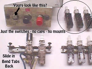
If you've got broken service switches... sheared off, sticking, poor contacts or whatever... on your Defender, or other Williams games, you can replace the switches individually to restore
them. All you need to do is gently pry the four tines that hold them in place up to a horizontal position & slide the broken switch out & insert a new one. Bend the holding tines back enough to keep it steadfastly in place & transfer your wires to the same positions on the new switch as they were on the old & you're back in business again.
I have replacement switches on the Parts Page at $2 each, but you'll have to use your old red or black button caps & these new switches do NOT replace the later WMs type that used white switches with poles on one side only.
Of all the ways I know of to make a game operate on free play, including cpu controlled, I think the best one is by using the 2 player start button which will work on a good 95% of games. Open your coin door & ID one of your coin switch wires that goes back to the pcb... not the ground wire that is looped to all switches... and then locate the wire leaving the player 2 switch & going back to the pcb. All you need to do is join these 2 wires together in some fashion. You can use splice connectors and a piece of 20ga wire to connect the two together. Getting fancy with this version, you could add an on/off switch on the inside of your coin door in-line with this circuit enabling you to flip the free play on & off when coin play was desired. You could go to the edge connector end of the harness to simply splice both lines together as they leave the pcb eliminating the need for a piece of wire. For all you shade tree techs... yes you can do it on-board, but you know I hate hacking up classics :-(
Once this is done, pushing the 2 player button will put up 1 credit to play a single game and pushing it a second time will start a 2 player game if desired. The reason that I prefer this method over the others, including dip switch free play, is that the games attract mode is left intact adding many years of life to the CRT's phosphor, i.e., less burn in on the screen.
I "hear" this a lot & it's usually accompanied by ... I just want to know which way is the correct way to put it in & don't care what it does, be it blocking, single, half or full wave rectification, or if it's just in there to add to the weight of my game! Here's a couple examples, maybe oversimplified, that should help you determine the correct way on your own. First I'll paste an excerpt from the WMs Battery Conversion Page that might prove to be of some help:
This will work in many other cases, but beware that you cannot just drop this in place of a ni-cad without defeating the charging system. This can be done by installing a blocking diode in the + line. I'm quite frequently asked how one can tell which way to install the diode. I think it is easiest for a newbie to think of the cathode stripe on the diode as a gate in the front yard fence that only opens outward as you are leaving your home, with the body being your walkway, of course. No one can walk up to your gate & pass through to enter your home, but you can walk down your walkway (diode body) and out through the gate. A diode with the complete symbol imprinted on it will have an arrow with it's point butted up to the cathode band signifying the direction of flow. If used as a blocking diode for a lithium battery you would want the cathode on the end furthest away from the + terminal, thus allowing the flow down the walkway to the components, but blocking at the gate any flow back towards the battery.
A common app that may even need 2 diodes would be coin meters, if used.
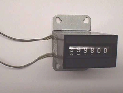
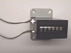
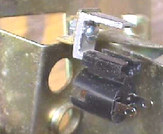
Your meter may have a diode installed inside to prevent spikes, called a clamping diode, and if it does, you'll find a + & - sign on the side where the wires come out as pic'd below.
Most meters with internal diodes will have color coded leads to aid in identifying polarity with red for the + side & black for -. The + side will connect to your voltage source, which should match the voltage rating found on the meter, as well. The - side will connect to your pcb's circuitry for pulsing the meter low (ground).
If your meter does not have the internal diode you can put your own across the 2 leads. Since you have no polarity at this time, it makes no difference which way you install it, but once installed, the cathode (banded end) becomes the + side & must connect to the power source. The other side will go to your drive circuitry of your pcb or whatever else you may be using.
If you want to install a coin meter & your PCB doesn't have any drive circuitry, you can connect it directly to the coin input circuitry. As your coin switch closes to pulse the input for your PCB, it also pulses the meter. This will work well with a 5 or 6 volt meter, but if you are using a 12 volt meter you do not want this 12 volts feeding back into your circuitry on your pcb & damaging it, so you can use another diode to prevent (block) this from happening. If you install a diode in the coin switch line coming from the PCB in the direction of the arrow with the banded side (cathode) towards the meter & coin switch it will block the 12 volts from feeding back into the board circuitry. Sound familiar.... it's the same blocking action used on the Tron/MCR battery conversion to stop the on-board charging system from feeding into the lithium battery.
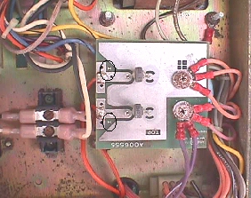
Here's a recently asked Q that will fit right in here, about replacing the diodes on an Atari xformer assembly for an Asteroids.
From the pic you can see that the older ones were not plainly marked with a band for the cathode side. They have a very thin pic of the symbol depicting the direction of flow on the side, but it is quite often worn away over time. In almost every instance you will find the symbols stamped on your PCB. In the case of this small PCB that mounts to the "Big Blue" capacitor, the symbols are very small themselves, so I circled them above. If you look closely you'll see the entry arrow butting up to the cathode band which faces the capacitor. This board with the 2 rectifiers forms a conventional full wave rectifier. Later Atari assemblies came with a full wave bridge rectifier. You might also note the + symbol on the pcb signifying the positive side for the Big Blue capacitor.
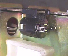
Coin door lamps & lamp sockets have been the source of many Qs over the past 8 years, and although I have addressed quite a few of them on my Help Page, this particular tip has not been covered & I think it's about time it was, so I'm jumping it to the top of the to-do-list.
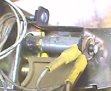
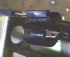
These are two of the common types of lamp sockets used on the coin doors. The older type on the left was a constant source of problems after many years in the field because of the sockets loosening up enough for the terminals to spin. They were slightly better than the ones used on the old WMs coin doors, but nevertheless, a problem. Ops used to bend them all out of shape when replacing the lamps & I'm sure that didn't help in any way.
Then later on when they saw that the newer type, as pic'd on the right, was holding up much better, they would remove the old sockets & bend the tab straight back to slide on one of the newer sockets, as pic'd below.
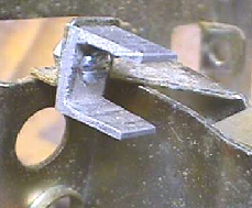
The trouble with this was that the bending of the tab weakened it so much that they often times broke clean off :-( I located some small "L" brackets meant for shelving at a local lumber store (pre-Home D) that worked out perfect when fastened in place of the old bayonet socket. You could just slip the newer wedge socket right onto it aligning perfectly. As is the case with so many good things, they simply disappeared from the store's inventory and said to be no longer available. The store chain is no longer now :-(
|ramble|
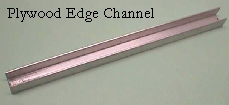
Sometime back in the day, I had read an article in one of the industry mags about using aluminum plywood channel over the piston rod of the pneumatic jukebox door lifters to prevent them from closing while your head was still inside them :-( Since my trusty short cue stick had once failed me, causing me to see many new stars that I hadn't seen before, I was keenly interested in this channel & ran out & purchased some to give it a try. I cut off a piece for a Rowe jukebox, opened the box, inserted the channel and it worked like a champ! I ended up stocking every size I could find & had cut pieces to the correct length for various brands & styles of jukes, labeling them as I went. I found many uses for this channel around the shop & in makeshifting parts that were hard to come by. This channel worked out well for this lamp socket mount, as well. |/ramble|
I never used a pattern for this, just cut them out as I needed them, but I'll put the basics here. First, I would drill a hole in the channel front about 3/16" from the end, centered, with a small step drill. I believe the first step is 1/8" if you're using a std drill bit. After the hole is drilled & any burrs polished away I would just slip the piece into the vise & cut off a piece of channel approximately 7/16" to 3/8"... always did it by eye & never had a problem, but you may want to get an exact measurement if you plan to try this.
I never bothered to cut off the upper unused portion, but I suppose you could take it a step further & remove it if you wanted to. If you don't have the original screw it can be fastened with a 1/4"x440 bolt & nut as pic'd above. The channel comes in various sizes to slip over the cut edges of plywood shelves... 1/4"... 3/8"... 1/2"... 3/4"... and the size used for this app is the 3/8". The channel can be found at Home Depot with some searching... seems no one that works there ever knows where, or what, this stuff is & it appears to be in a different location in every store :-(
I see that lots of you have trouble with the types of lamps & sockets, along with the voltage that is used to power them, so I'll insert a brief comment here on this subject. First the bayonet type is a lamp with a smooth cylinder base that has two projecting pins which fit into slots on the holder & when twisted a quarter turn, lock themselves into the socket. Bayonet lamps would be #44 or #47 when used in a 5 to 6VDC or 6.3VAC circuit, and when powered by 12 volts you'd need a lamp such as the #1813. The wedge type is as implied, a wedge lamp is pushed straight into the socket & has a chisel-shaped base, as opposed to, the cylindrical bayonet type. One loop of exposed wire to either side of the wedge base makes contact in the socket. Wedge lamps used in a 5 to 6VDC or 6.3VAC circuit would be #555 & in a 12 volt circuit you'd need #161 lamps.
As for voltage needed in your particular cab, even if there are no lamps in it & you have no manual or schematics, you can always measure the voltage right across the two wires that feed the lamp... right at the socket. If you own a game you should have a meter, but on the off chance that you don't, any meter should do the trick, even a small pocket-sized $5 analog meter from your local electronics store.
Help Page Index Big Bear's Bulletin Board
Site Index
What's the common for?
in the video bundle, the coin door bundle, player 1 bundle, player 2 bundle
and for the speaker...so any switches used for player 1 controls are in a
loop of their own from the first switch to the last switch & back to the
start point on the first switch. If any one ground loop breaks it will still make contact in the opposite direction & if all switches fail in that loop I know
it is between my first switch & the edge connector... the only lone common
ground wire & easily identified by the junction of 3 black ground wires - in
from PCB, start of ground loop & the closing ground loop wire. A *lasso*
arrangement, so to speak.
-----------------------------------------------------------
Symptom: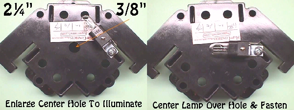
