|
Over the years I've read hundreds of emails about using another game in your collection to locate a problem you have with your favorite game. Many do this the hard way & I've already written about using monitor extensions because so many were telling me how they pulled the monitor from one to put in another just to eliminate it as the problem child :-( Obviously, going to all that work can also be detrimental to both the monitor & yourself, should it be accidentally bumped or dropped during this process, hence, the article on using an extension. Another very common thread in emails is the tranferring of the power supply board and/or transformer assembly between games from the same manufacturer. A typical scenario includes the above mentioned monitor and starts out something like this.... I have a Stargate that has squiggly lines [insert your symptom here] on the screen & I've taken the monitor out of my Robotron & tried it in the Stargate with the same results. I swapped out the power supply board & still had the same results :-( Can I transfer the wiring harness & transformer between the games? Another example would be... I have a Stargate with a light bar scrolling through the pic & I don't think it's the power supply because I measure 5 volts with my meter & I know it's not the monitor because I swapped in a good spare & it made no difference. In case it is the power supply can I make my Galaga power supply work in the cabinet? There are many varieties of this Q including the simplest one of how can I be sure I'm getting clean power to my Stargate because I have a ripple coming from somewhere. Well... you can use one of your other game's DC power source to rule out power supply problems, but this is a task no matter how you do it, so the easier way is to test the power supply that is in question. I've explained how to do this in email many times by using an old JAMMA harness that you may have laying around, perhaps from one you needed to change out. For those who did not, I made up harnesses for them. Back in February I made one of these harnesses for a collector & shortly after he received it he ordered 2 more for fellow collectors who had seen his & asked why I didn't have it on the Parts Page... encouraging me to add it, but I didn't want to until I had the time to write it up in more detail. Soooo.... Here's how you can do it! All you really need to see is that the 5 volts is clean enough to drive a PCB. Minus 5 volts & 12 volts are usually used for biasing audio circuits, so they are not really needed when testing. There are so many cheap JAMMA boards floating around these days that you can easily find one to be your test board. The basic requirements for testing purposes are power to drive the board & video to enable you to see the results, hence an old replaced JAMMA harness since I/O lines are not needed & are usually the cause for the replacement. I don't have any old JAMMA harnesses kicking around to use for this, so I'll walk through the harness portion with a new one & if you have an old one you can see what needs to be remove from it.
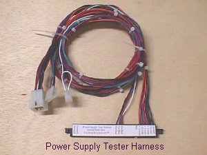
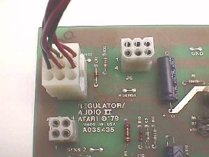
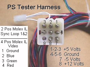
As I said, basic power & video bundles are all you need & with a standard 5' harness using separate bundles you will have approximately a 10' reach between games. Of course, you can connect back to the same game monitor to eliminate wiring, break connectors & PCB as suspect. If you're starting out with a used JAMMA harness you can remove any I/O lines that are not necessary making this much easier to handle & store. For the video termination if you use a 4 position & a 2 position Molex .156 housing you'll be able to mate up to just about any monitor's header. As you know from the Monitor Extension Page there are a few exceptions, but chances are you'll always have a suitable monitor & by using the 2 & 4 position connectors you can adapt to any situation. For example, the 2 connectors will fit side-by-side for a +sync connection such as the Stargate & other WMs games of that era. With the looped sync connection in the 2 position connector you can easily hook up to a separate header with -sync input such as the G07 monitor uses. To go a step further, when hooking up sync to a K7000 chassis where only the HSYNC is used for composite sync, the 2 position can hang out over P6 of the header into the keyway to supply the single composite +sync connection, or it can hang out over the 10th position of the header for composite -sync. In power handling you'll want a base break connector to work from for different power supply hookups. This allows rerouting lines to their correct positions, so that you don't need a harness for every type PS you want to test. I've always used the Molex .093 housing... the 3x3 in the pic of my harness above... since the first PC-type supply was introduced to the arcade game. The reason is simply because the mfrs followed an assigned pinout & this allows for the test harness to plug into any PC-type power supply directly & unadapted. This type PS is easy to use outside of a game cab, as well, because of the 2 simple connections to AC in & DC out. Any PS you want to test can easily adapt to the PC-type 3x3 connector.
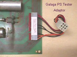
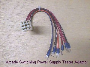
The adaptor above will utilize the Galaga's linear power supply to the test harness' 3x3 DC power input. By using this power to drive your JAMMA test PCB & feeding the video to a known good monitor, whether in another of your games or just a spare monitor sitting out of a cab, you'll be able to see whether, or not, the DC power is clean. If you get the same crappy looking pic when hooked up this way, you've proven out that the Galaga's PS is the fault.
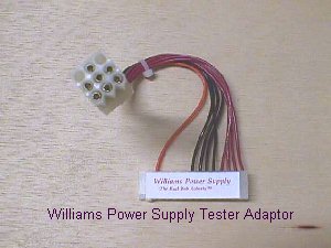
This adaptor is for the Williams linear power supplies & serves the same purpose, as does each type of PS adaptor, simple rerouting of power lines to their appropriate destinations.
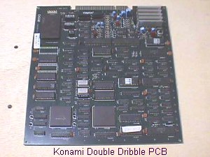
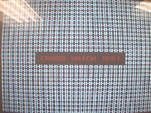
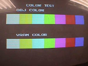
Now that you have a harness all that remains is to select a JAMMA PCB to use for a test board. I always liked the older Konami boards for this because of their built-in generator supplying all the testing aids needed.
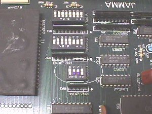
If you color in the 2 dip switches that control normal operation or test mode it'll be easy for you to swap between the two modes.
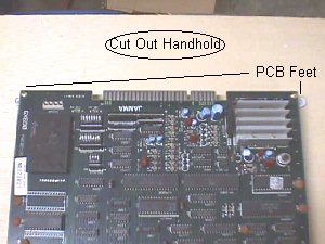
If you're one who spends as little as possible on a testing aid, saving every extra penny for that new game you've been wanting, you can simply cut a piece of cardboard the size of the PCB & cable tie it to the solder side to protect the PCB from shorting to anything when handling it. If this isn't for you, you can always mount the PCB on a piece of plywood & even cut out a handhold to tote it around by.
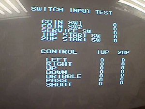
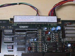 The pic above shows the basic harness connected to the Konami PCB, but in order to change test screens you'll need to add an I/O line to 1P start, since it is the advance switch in test mode.
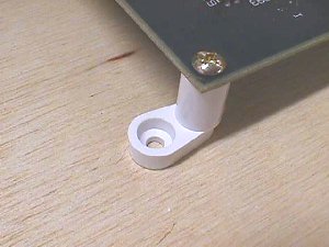
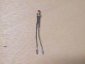
The easiest way to add the switch is by using a small momentary switch such as the one above.
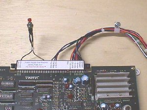 Just slip one lead into a ground position on the JAMMA connector & the other one into the 1P start position. You can add a switch this way if you use another PCB that may have test screens by simply placing it in the correct I/O line, i.e., if "test" or "service" control these features on your PCB, just pin it to the appropriate position on the JAMMA edge connector. The pic above shows both bundles leaving the right side of the tote board thru a cable clamp... this is just to highlight the added I/O switch & you should use a cable clamp on either side with bundles separated for maximum mobility. The only other thing I can think of that may help you build your own is putting the basic pinouts here to save you from looking them up.
If you are one of those that rather have it ready made you'll find it on the Parts Page here. |